


- 28 -
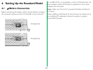
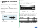
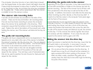
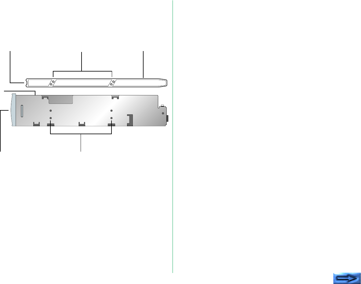
Both sides of the internal-mount scanner are identical as shown
below. Note the set of two tapped holes on each side. One
set of holes on each side of the scanner will be used for the rails
as shown in this figure.
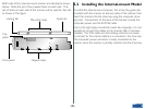
5.2 Installing the Internal-mount Model
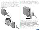
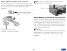
To install the internal-mount scanner, first screw the guide rails
provided with the scanner to the two sides of the scanner, then
insert the scanner into the drive bay using the computer drive
bay slots. Connections to the back of the scanner include the
computer power and the SCSI flat cable.
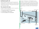
Due to the tight space constraints inside the computer, it is not
possible to connect the cables to the scanner after it has been
installed. The SCSI cable and terminating networks are easier
to connect to the scanner before it is mounted in the drive bay.
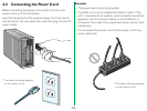
The computer power connector is easily connected to the
scanner when the scanner is partially inserted into the drive bay.
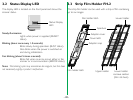
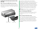
Guide rail
Mounting holes
Locking tab
Front panel Tapped holes
Top
panel