10
2-2 Using Link Adaptors
In a PC Link System, Link Adapters are used whenever more than two PC
Link Units are connected in any one PC Link Subsystem. They are also used
to enable optical links between PC Link Units to provide greater transmission
distance and greater noise resistance. When using Link Adaptors, refer to
the Link Adaptor Installation Guide.
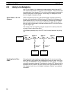
A PC Link System can be set up to take advantage of optical communica-
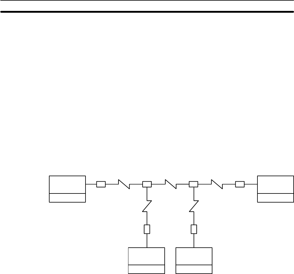
tions by using combinations of Branching and Converting Link Adapters. As
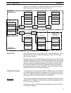
shown below, each PC Link Unit is connected to a Converting Link Adapter
that converts to optical communications. Optical fiber cable is then used to
form the main line and branch lines that connect each PC Link Unit-Convert-
ing Link Adapter pair.
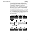
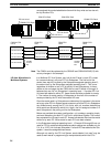
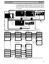
The straight lines in the following diagram represent wire cables; those with
zig-zags in them, optical fiber cable.
In the following example, any of the PC Link Units may be set as the polling
unit.
PC Link Unit
C-series PC
PC Link Unit
C-series PC
PC Link Unit
C-series PC
PC Link Unit
C-series PC
AL004 Link
Adapter
AL004 Link
Adapter
AL004 Link
Adapter
AL002 Link
Adapter
AL002 Link
Adapter
AL004 Link
Adapter
Optical fiber
Although special characteristics of optical fibers call for care in connecting
optical devices, laying optical fiber cable basically does not differ from laying
wire cable. All OMRON PCF and the 3G5A2-PF101 APF (length: 1 m) cable
come with connectors attached. Connectors for all other APF cables must be
assembled by the customer. As using Optical Fiber cable requires the use of
Link Adaptors, refer to the Link Adaptor Installation Guide for more detailed
information.
Optical Cable in PC Link
Systems
Handling Optical Fiber
Cable
Using Link Adaptors Section 2-2


