63
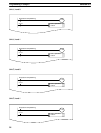
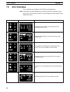
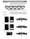
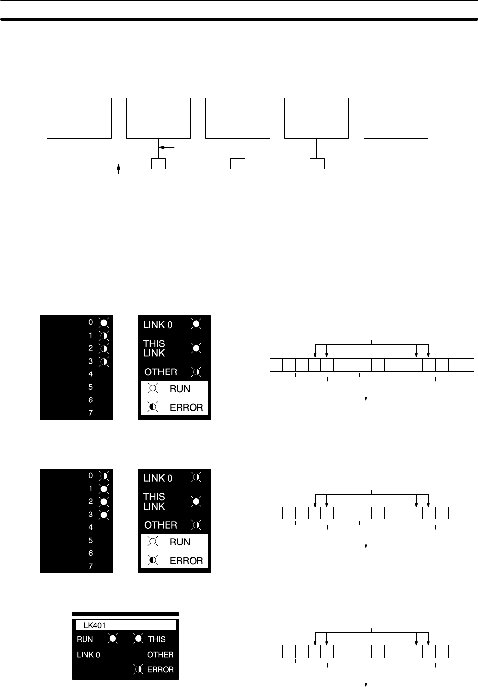
This example will describe error indications on all PC Link Units using the
following System configuration. Transmission line breaks will be described at
two different points, A and B. Unit 3 has been set for double allocation, and
thus is allocated the LR bits and flags from both Unit 3 and Unit 4.
C2000H PC
Unit 0,
(polling unit)
C200H PC
Unit 3
C500 PC
Unit 1
C500 PC
Unit 2
(B)
(A)
C200H PC
Unit 5
Double allocation
The C200H could be replaced by the C200HS and C200HX/HG/HE(-Z) with-
out any changes in this example.
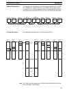
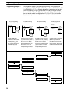
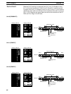
Because Unit 0 receives no response from Units 1, 2, 3, and 5 it indicates an
error for all of them. Because Units 1, 2, 3, and 5 receive no polling signal
from Unit 0, they each indicate an error for it. LED indications are shown be-
low, as well as the conditions of the PC RUN and Error Flags in the SR area.
Unit 0 (C2000H PC)
1100 11111100 1110
Bit 15 Bit 0
Word 250
Error Flags ON
for Units 1 to 5
Error Flag OFF
for Unit 0
PCs operative
for all Units
Display pattern A Display pattern B
Allocated to Unit 3.
Units 1 and 2 (C500 PC)
1100 11110000 0001
Bit 15 Bit 0
Word 62
Error Flags OFF for
Units 1 to 5
Error Flag ON for
Unit 0
PCs operative
for all Units
Display pattern A Display pattern B
Allocated to Unit 3.
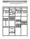
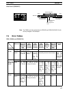
Units 3 and 5 (C200H PC)
1100 11110000 0001
Bit 15 Bit 0
Word 250
Error Flags OFF
for Units 1 to 5.
Error Flag ON for
Unit 0.
PCs operative
for all Units.
Allocated to Unit 3.
System Configuration
Note
Break at Point A
Error Examples Section 7-2


