56
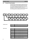
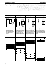
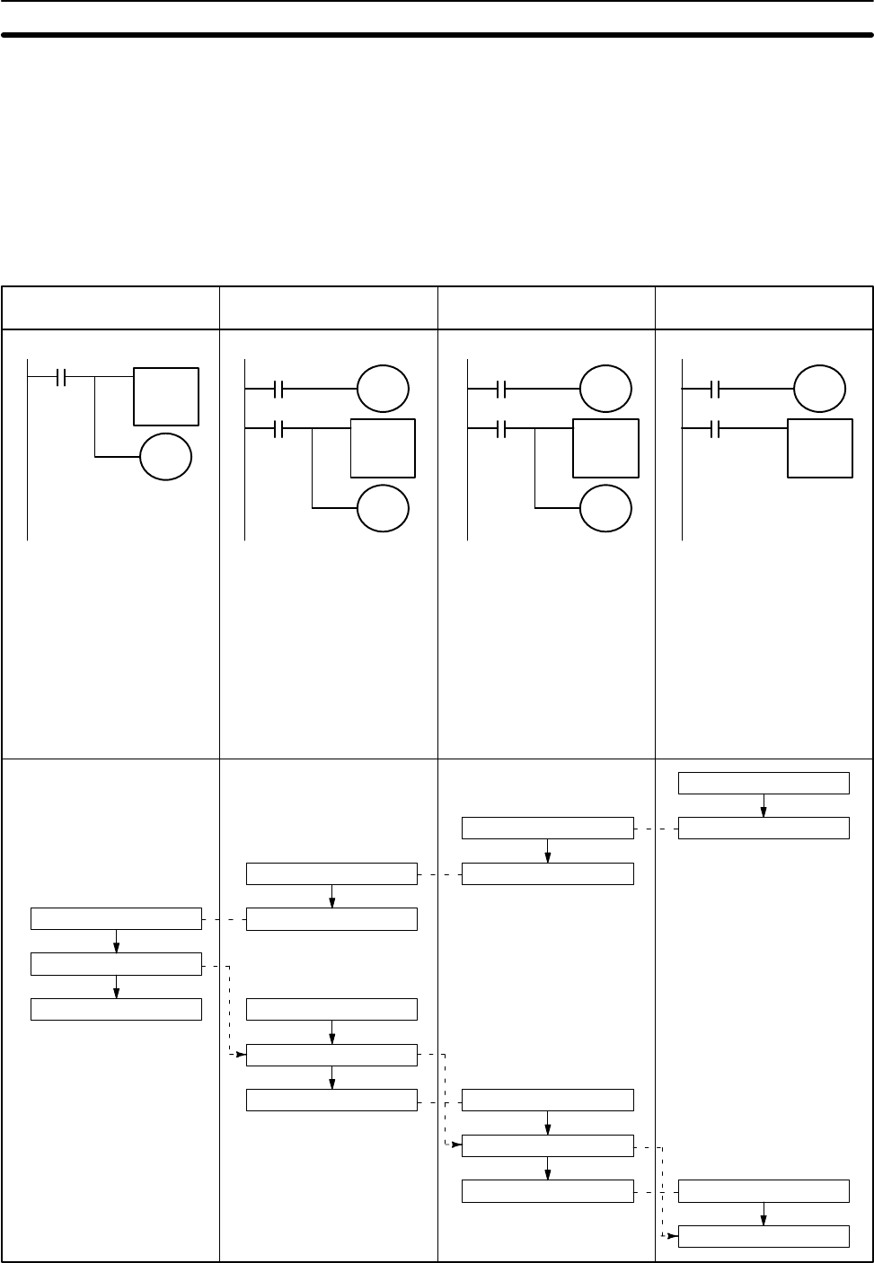
Using the above System, the following programming, which is started by
turning ON input 0000 in PC (D), will move the contents of DM 0100 from PC
(C) to DM 0000 in PC (D). In the table below, the process starts at the right
when PC (D) sends a START signal is sent to PC (B). This signal is trans-
ferred across the PCs to PC (C) (at the extreme left in the table below) and
then the transfer of data is instigated from PC (C) to PC (D) (right to left in
the table below.)
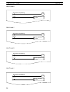
MOV(21)
DM 0100
LR 14
LR
1500
LR 0100
MOV(21)
LR 14
LR 35
LR
3600
LR 1500
LR
0100
LR 5000
LR
0015
LR
5000
MOV(21)
LR 35
LR 01
LR 3600
LR 1400
LR
1400
MOV(21)
LR 01
DM 0000
LR 0015
0000
Start input
0000 ON
LR 1400 ON
LR 1400 ON
LR 5000 ON
LR 5000 ON
LR 0100 ON
LR 0100 ON
DM 0100→LR 14
LR 1500 ON LR 1500 ON
LR 14
→LR 35
LR 3600 ON
LR 3600 ON
LR 35
→LR 01
LR 0015 ON
LR 0015 ON
LR 01
→DM 000
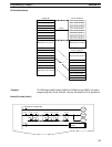
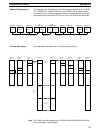
PC (C) Programming PC (A) Programming PC (B) Programming PC (D) Programming
Contents of DM 0100 is
transferred to LR 14 and the
Completed flag, LR 1500
(defined by the program-
mer), is turned ON when LR
0100 (written by PC(A))
turns ON.
A START signal is sent to PC
(C) when LR 5000 (written by
PC (B)) turns ON. When
transfer of DM 0100 data has
been completed at PC (C),
the contents of LR 14 is
transferred to LR 35 and the
Completed flag, LR 3600, is
turned ON.
A START signal is sent to PC
(A) when LR 1400 (written by
PC (D)) turns ON. When
transfer of LR 14 data to LR
35 has been completed at PC
(A), the contents of LR 35 is
transferred to LR 01 and the
Completed flag, LR 0015, is
turned ON.
A START signal is sent to PC
(B) when input 0000 turns
ON. When transfer of LR 35
data to LR 01 has been com-
pleted at PC (B), the contents
of LR 01 is transferred to DM
0000.
Programming Example 1
Programming Examples Section 6-3


