13
3-2 LR Area Allocations
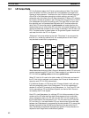
To enable data transfer between PCs in an PC Link System, part of the LR
area is allocated as the write area for each PC in the System. Which and how
many LR words are allocated to each PC are determined by switch settings,
which are described in 4-2-2 Switch Settings. This section describes the
method for allocating words assuming that each PC is allocated the maxi-
mum number of words possible.
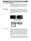
If a System contains PCs that have different sizes of LR areas, only the
words that are common to both areas are used in actual PC Link communi-
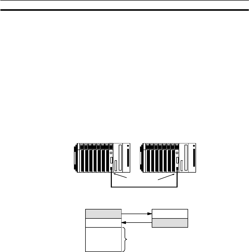
cations. In the following example, the LR areas of each PC are illustrated
below it. Words labeled “work words” are not used by the PC Link System
and are available for use in programming if required. As shown, the rest of
the LR area is divided with the smaller LR area of the other PC to form the
write words for each.
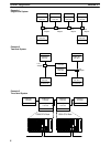
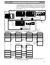
C1000H CPU Rack C500 CPU Rack
PC Link Units
Work words
LR 08 to LR 15
C1000H CPU C500 CPU
LR 00 to LR 15
LR 32 to LR 63
LR 16 to LR 31 LR 16 to LR 31
LR 00 to LR 15
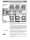
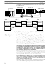
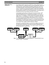
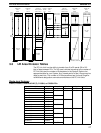
The following example combines one C2000H PC, two C500 PCs, and a
C200H PC in a Single-level System using 128 LR bits per PC. The PC Link
Unit on the C2000H PC at the left end of the System has been designated as
the polling unit. The C500 PCs, providing the smallest LR areas, limit the
number of bits that can be transferred via the PC Link Units. Because the
C500 PC has only 32 words, only words 00 through 31 may be used in the
C2000H PCs (Units #0 and #2). The C2000H and C200H LR words that are
not used (32 to 63) may be used as work bits in programming. The LR word
allocations for each PC Link Unit are given below it. The shaded area is the
section of the LR area written to by the PC Link Unit. The arrows indicate
data flow.
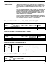
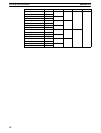
In this example, data written to words LR 8 through 15 by the PC to which PC
Link Unit 2 is mounted is automatically transmitted to words LR 8 through 15
in the other PCs. While the PCs for PC Link Units #0, #1, and #3 are able to
read this data freely, they cannot write in this area. All of the other PCs also
LR Area Allocation in
Mixed-PC Systems
Single-level System
LR Area Allocations Section 3-2


