6.3.3. ROM (IC2)
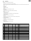
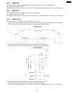
This 128 KB ROM (OTPROM or MASKROM) has 32 KB of common area and bank area (BK4~BK15).
The capacity of each bank is 8 KB.
The addresses of the common area are from 0000H to 7FFFH, and addresses 8000H to 9FFFH are for the bank area.
6.3.4. RAM (IC3)
This 32 KB RAM has 8 KB of common area and bank area (BK0, BK1).
The capacity of each bank is 12 KB.
The addresses of the common area are from D000H to EFFFH, and addresses A000H to CFFFH are for the bank area.
6.3.5. Reset Circuit
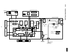
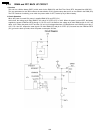
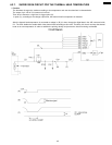
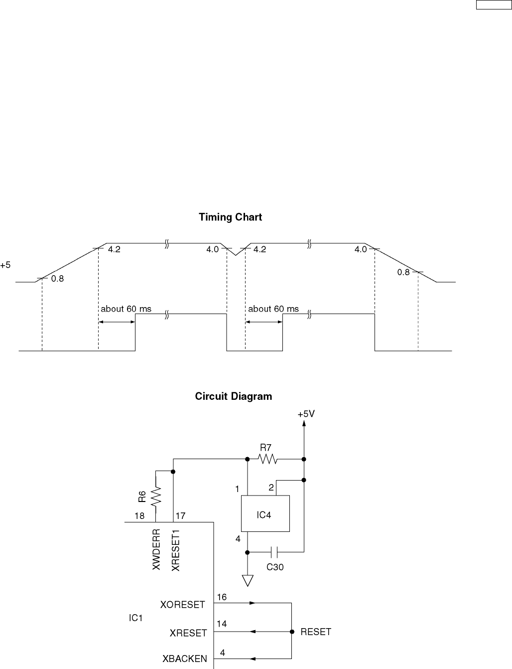
The output from pin 1 of the Reset IC (IC4) resets the gate array (IC1).
1. During a power surge, a positive reset pulse of 175 msec or more is generated and the system is reset completely.
This is done to prevent partial resetting and system runaway during a power fluctuation.
2. When pin 1 of IC4 becomes low, it will prohibit the RAM (IC3) from changing data.
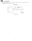
The RAM (IC3) will go into the backup mode, when it is backed up by a lithium battery.
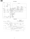
3. The watch dog timer, built-in the gate array (IC1), is initialized about every 1.5 ms.
When a watch dog error occurs, pin 18 of the gate array (IC1) becomes low.
The terminal of the WDERR signal is connected to the reset line so the WDERR signal works as the reset signal.
105
KX-FT21RS


