


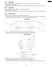
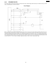
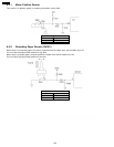
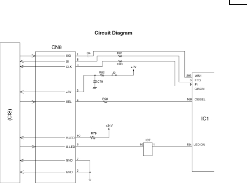
6.4.4. SCANNING BLOCK
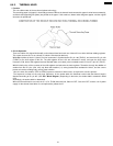
The scanning block of this device consists of a control circuit and a contact image sensor made up of a celfoc lens array, an LED
array, and photoelectric conversion elements.
When an original is inserted and the start button pressed, pin 154 of IC1 goes to a high level and the transistor inside IC7 turns on.
This applies voltage to the LED array to light it. The contact image sensor is driven by each of the FTG-F1 signals output from IC1,
and the original image illuminated by the LED array undergoes photoelectric conversion to output an analog image signal (AIN).
The analog image signal is input to the system LSI (IC1) on ANA1 (pin 205 of IC1) and converted into 8-bit data by the A/D
converter inside IC1. Then this signal undergoes digital processing in order to obtain a high-quality image.
113
KX-FT21RS