


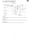
6.9. ITS (Integrated telephone System) and MONITOR SECTION
6.9.1. GENERAL
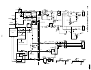
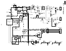
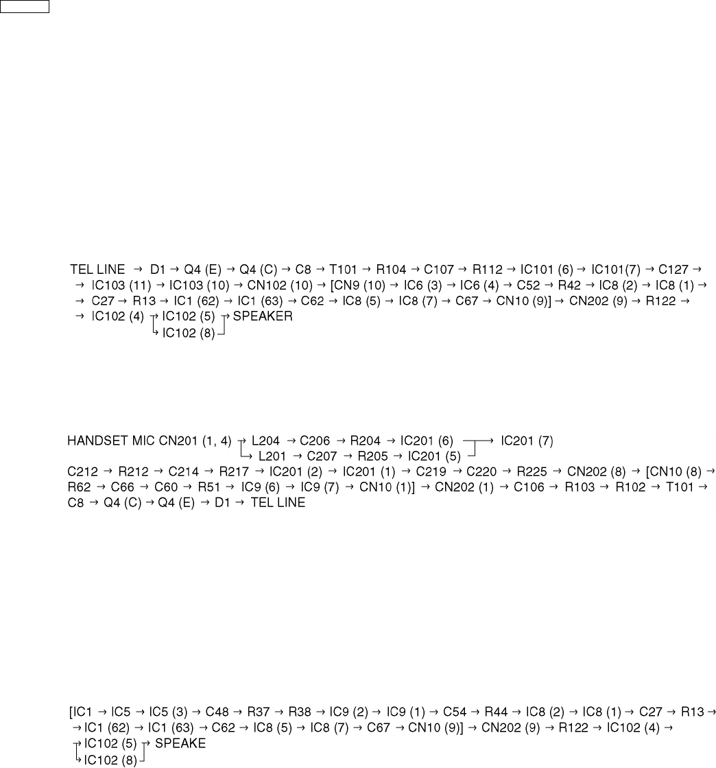
During the monitor operation, the speaker output passes through the power amplifier (IC102) [Analog board].
The DTMF signal is output from the modem (IC1: digital board). The alarm tone, the key tone, bell tone, and beep are output from
gate array IC1 (digital board). During a pulse dial operation, the monitor tone is output from gate array IC1.
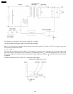
6.9.2. MONITOR CIRCUIT
1. Function
This is the function when you are not holding the handset and can hear the caller´s voice from the line.
2. Circuit Operation
(Monitor Signal Path)
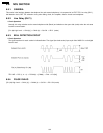
6.9.3. HANDSET CIRCUIT
1. Transmission signal
2. Reception Signal
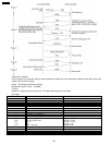
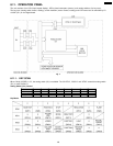
TEL LINE → D1 → Q4 (E) → Q4 (C) → C8 → T101 → R104 → C107 → R112 → IC101 (6) → IC101 (7) → C127 →
IC103 (11) → IC103 (10) → CN102 (10) → [CN9 (10) → IC6 (3) → IC6 (4) → C52 → R42 → IC8 (2) → IC8 (1) → C27 →
R13 → IC1 (62) → IC1 (63) → C62 → IC8 (5) → IC8 (7) → R60 → C63 → IC6 (8) → IC6 (9) → C65 → CN10 (10)] →
CN202 (10) → J402 → C234 → R209 → Q201 (B) → Q201 (E) → C205 → L202 → HANDSET SPEAKER
6.9.4. MONITOR CIRCUIT
1. DTMF Monitor
(Monitor)
(Handset)
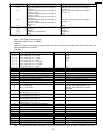
[IC1 → IC5 → IC5 (3) → C48 → R37 → R38 → IC9 (2) → IC9 (1) → C54 → R44 → IC8 (2) → IC8 (1) → C27 →
R13 → IC1 (62) → IC1 (63) → C62 → IC8 (5) → IC8 (7) → R60 → C63 → IC6 (8) → IC6 (9) → C65 → CN10 (10)] →
CN202 (10) → J402 → C234 → R209 → Q201 (B) → Q201 (E) → C205 → L202 → HANDSET SPEAKER
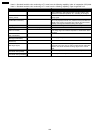
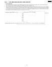
2. Alarm/Beep/Key tone/Bell
[IC1 (59) → R28 → C45 → R35 → IC8 (2) → IC8 (1) → C27 → R13 → IC1 (62) → IC1 (63) → C62 → IC8 (5) → IC8 (7) →
C67 → CN10 (9)] → CN202 (9) → R122 → IC102 (4) → IC102 (5) → SPEAKER
3. Dummy Ring Back Tone
Same with the modem signal transmission.
132
KX-FT21RS