


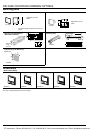
COUNTER-RELATED TERMINOLOGY
TYPES OF COUNTERS
1. Electro Preset Counter
The counter is equipped with semicon-
ductor counting circuitry. When the
counter counts up to a preset number, its
output circuit sends a signal.
2. Electro Magnetic Counter
A magnet is magnetized and demagne-
tized to drive the dial and count up num-
bers.
RATING
1. Rated Operating Voltage
The voltage is applied to start the
counter.
COUNTINGS
1. Pulse
This is a voltage or current signal sent at
intermittent time intervals.
2. Count
Pulses are used to count up and down.
3. Miss-count
This happens if the number of pulses
does not correspond to the number of
counts.
4. Hertz
This unit of counting speed is used to
give the number of counts per one
second.
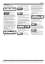
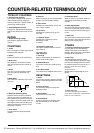
5. Make Ratio
This is the ratio of ON time (Ta) to OFF
time (Tb).
6. Maximum Counting Speed
Suppose that the counter is operated
with an input pulse of a make ratio of 1.
The highest counting speed is the peak
of a range in which the output circuit can
send signals without mis-counting. The
speed is expressed in units of Hz (cps:
counts per a second).
7. Over Count
Counting continues beyond a preset
number.
8. Recount
When counting is up, the counter display
resets to zero and counting restarts.
9. Down Count
Numbers are counted down one by one
from a preset number.
10. Up Count
Numbers are counted up one by one
from zero.
11. Up/Down Count
Numbers are counted up or down
depending on input
conditions.
12. Rejection (gate) Input
This signal is used to keep the counter
from counting.
OUTPUTS
1. Count Up
When a preset number is reached, the
output circuit sends a signal.
2. Retained Output
The output is held until a reset signal is
sent.
3. One Shot Output
This output has a specified width of time.
RESETTINGS
1. Reset
The counting process, display and output
sections are all brought back to the initial
status.
2. Power off Reset
The operating voltage is turned off to
reset the counter.
3. Manual Reset
The counter is manually reset.
4. Remote Reset
A signal is sent from a remote point to
the reset terminal so as to reset the
counter.
5. Automatic Reset
When counting is up, internal circuitry is
activated to automatically reset the
counter.
6. Reset Signal Width
This is the time during which the power
is off so as to reset the counter or during
which an external (manual) reset signal
is sent.
7. Reset time
This is the time from the moment a reset
signal is sent to the instant the counter is
ready to start counting again.
OTHERS
1. Function of Memorizing Condition
Counting data up until the operating
voltage is turned off can be stored in
memory. When the power is reactivated,
the data can be reproduced.
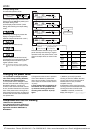
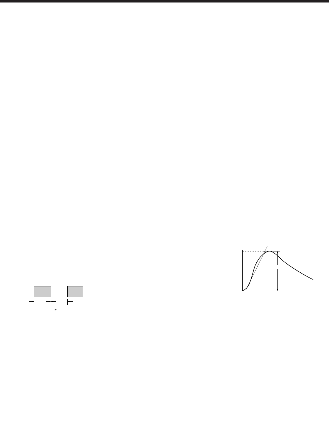
2. Anti-surge
The strength against power voltage
surge is determined by applying a single-
pole full-wave voltage (several hundred
to several thousand volt wave for ±(1.2 ×
50) µs) acrosss the control power
terminals.
Surge waveform
[Single-pole full-wave voltage for ±(1.2 ×
50) µs]
3. Noise Immunity
This is the strength against external
noise. Relay noise tests, noise simulator
tests, etc. are conducted.
Ta
Time
Tb
0 1.2 50
Time
(
µs
)
50
30
Surge voltage
(
%
)
0
100
90
Peak value
CTi Automation - Phone: 800.894.0412 - Fax: 208.368.0415 - Web: www.ctiautomation.net - Email: info@ctiautomation.net