


145
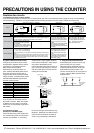
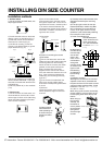
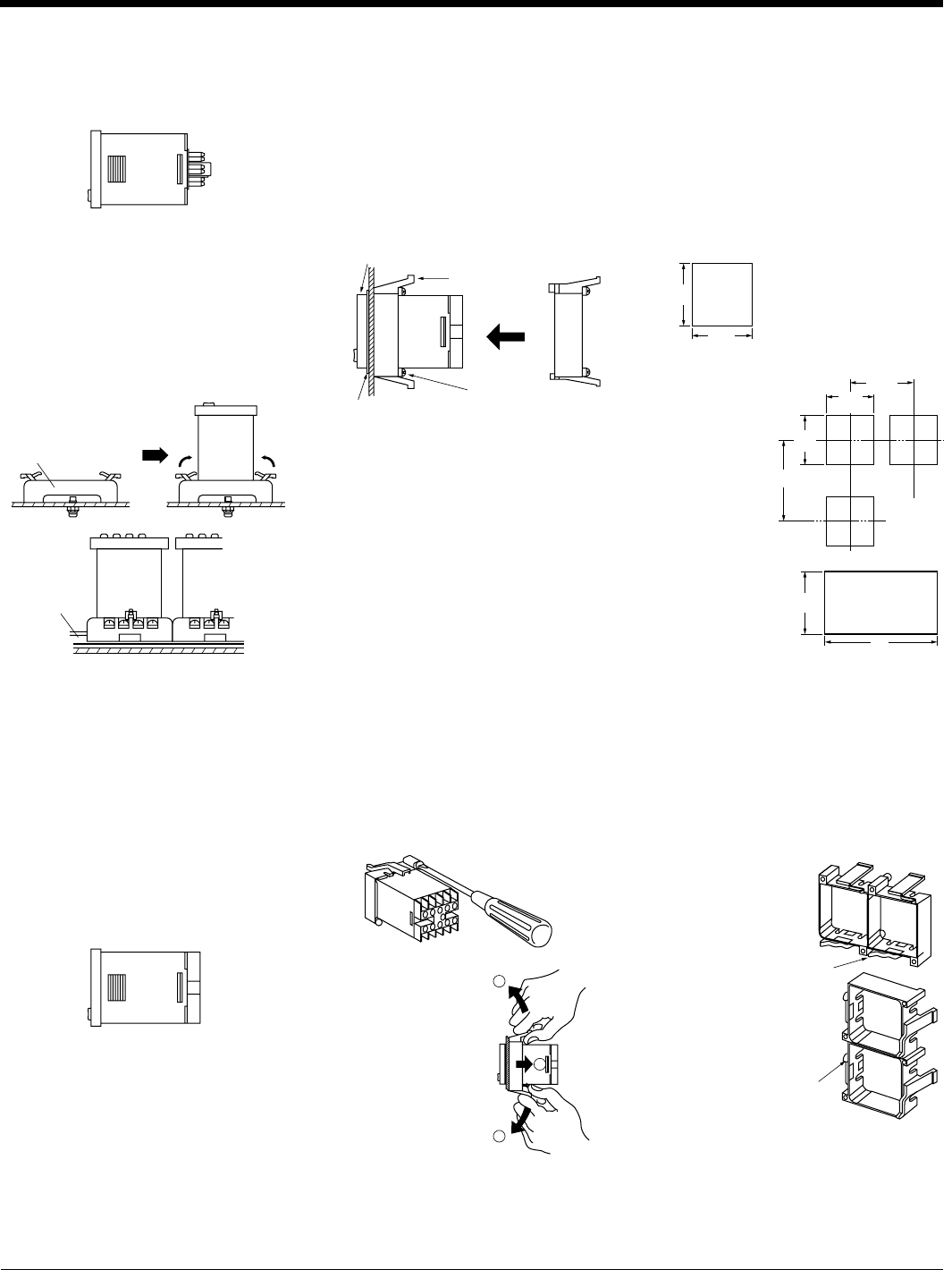
Installation methods
1. Surface mount
1) For the counters of LC4H series, use
the pin type counter.
INSTALLING DIN SIZE COUNTER
5) Correctly connect the terminals while
seeing the terminal layout and wiring
diagram.
6) If the pin type is used, the rear pin-
bracket (AT8-RR) or the 8P cap (AD8-
RC) is necessary to connect the pins.
For the 11-pin type, use the 11P cap
(AT8-DP11) and avoid directly soldering
the round pins on the counter.
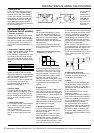
7) Panel cutout dimensions
The standard panel
cutout dimensions are
shown in the left fig-
ure. (Panel thickness:
1 to 5 mm .039 to .197
inch)
8) Although the
counters can be
mounted adja-
cent to each
other in this
case, it is rec-
ommended to
arrange the
mounting holes
as shown in the
figure to facili-
tate attaching
and detaching
the mounting
frame.
9) Adjacent mounting
Although the counters can be mounted
adjacent to each other, remember that
the panel surface of LC4H series counter
will lose its water-resistant effect. (Panel
thickness: 1 to 5 mm .039 to .197 inch)
A = (48 × n – 2.5)
When lining up the counters horizontally,
set the frames in such a position so the
formed spring areas are at the top and
bottom.
When lining up
the counters
vertically, set
the frames in
such a position
as the formed
spring areas
are at the right
and left.
+0.6
+0
Pull the mounting
frame backward
while spreading out
its hooks with your
thumbs and index
fingers.
3) Caution in mounting the counter
• LC4H series
ࠗa If the LC4H series are used as the
waterproof types (IEC IP66), tighten the
reinforcing screws on the mounting
frames so that the counters, the rubber
gaskets, and the panel surfaces are
tightly contacted with each other.
(Tighten the two screws with uniform
force and make sure that there is no rat-
tling. If the screws are tightened too
excessively, the mounting frame may
come off.)
ࠗb If the counter is installed with the
panel cover and the rubber gasket
removed, the waterproofing characteris-
tic is lost.
4) Removal
Loosen the screws on the mounting
frame, spread the edge of frame and
remove it.
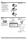
2) How to mount the counter
From the panel front, pass the counter
through the square hole. Fit the mount-
ing frame from the rear, and then push it
in so that the clearance between the
mounting frame and the panel surface is
minimized. In addition, lock the mount-
ing frame with a screw.
• LC4H series
5) 8-pin type should be connected with
terminal socket AT8-DF8K. 11-pin type
should be connected with terminal sock-
et AT8-DF11K.
6) DIN rail (AT8-DLA1) is also available
(1 m).
2. Flush mount
1) For the counters of LC4H series, it is
recommended to use the built-in screw
terminal type for flush mount. (Mounting
frame and rubber gasket are provided
when counter is shipped.)
2) Put the terminal socket on the board
directly or put it on the DIN rail (Fig. 1).
3) Insert the counter into the terminal
socket and fix it with clip (Fig. 2)
4) On DIN rail mounting, mount the
counter on the DIN rail tightly to get the
proper dimension (Fig. 3).
45
1.772
+0.6
0
+.024
0
45
1.772
+0.6
0
+.024
0
45
1.772
Min. 80
3.150
Min. 80
3.150
+0.6
0
+.024
0
45
1.772
+0.6
0
+.024
0
45
1.772
A
+0.6
0
+.024
0
Formed spring
Formed spring
Terminal socket
(Fig. 1) (Fig. 2)
DIN rail
(Fig. 3)
Mounting flame
Rubber
Panel cover
Screw
PUSH
gasket
1
2
1
CTi Automation - Phone: 800.894.0412 - Fax: 208.368.0415 - Web: www.ctiautomation.net - Email: info@ctiautomation.net