


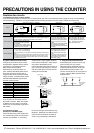
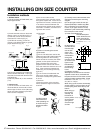
PRECAUTIONS IN USING THE COUNTER
Cautions for circuits
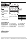
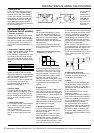
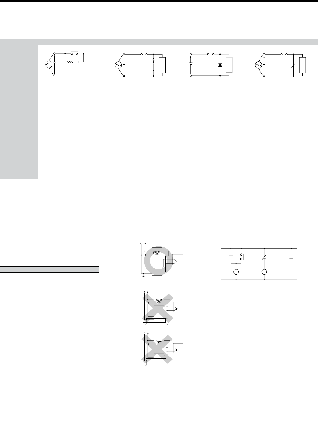
1. Protective circuit for counter contact
In the circuit that switches an inductive load, a contact failure may occur at a contact point due to surge or inrush current resulting
from that switching. Therefore, it is recommended that the following protective circuit be used to protect the contact point.
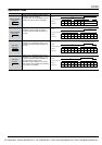
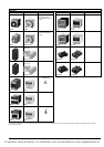
2. Type of Load and Inrush Current
The type of load and its inrush current
characteristics, together with the switch-
ing frequency, are important factors
which cause contact welding.
Particularly for loads with inrush cur-
rents, measure the steady state current
and inrush current and use a relay or
magnet switch which provides an ample
margin of safety. The table below shows
the relationship between typical loads
and their inrush currents.
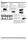
various kinds of input signals, therefore,
use a power transformer in which the pri-
mary side is separated from the
ungrounded secondary side as shown in
Fig. A, for the power supply for a sensor
and other input devices so that short-cir-
cuiting can be prevented.
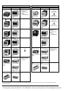
4. Long Continuous Current Flow
Avoid keeping the counter on for a long
period of time (over one month).
Otherwise heat is generated and accu-
mulated inside the counter, which may
deteriorate its electronic parts. If the
counter must be kept on for a long period
of time, a relay is added. See the circuit
diagram below.
When you want large load and long life
of the counter, do not control the load
direct with a counter. When the counter
is designed to use a relay or a magnet
switch, you can acquire the longer life of
the counter.
3. Connection of input
(Except for LC4H-S/AC type)
The LC4H series use power supply with-
out a transformer (power and input termi-
nals are not insulated). In connecting
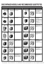
CR circuit (r: resistor c: capacitor)
Counter contact
(see note.) Available Not available Available
Counter contact Counter contact Counter contact
Circuit
Application
Features/Others
Device Selection
AC
Available
If the load is a relay or solenoid, the release time lengthens.
Effective when connected to both contacts if the power supply voltage is
24 or 48 V and the voltage across the load is 100 to 200 V.
If the load is a timer, leakage current
flows through the CR circuit causing
faulty operation.
Note: If used with AC voltage, be sure
the impedance of the load is sufficiently
smaller than that of the CR circuit.
As a guide in selecting r and c,
c: 0.5 to 1 µF per 1 A contact current
r: 0.5 to 1 Ω per 1 V contact voltage
Values vary depending on the properties of the load and variations in counter charac-
teristics.
Capacitor c acts to suppress the discharge the moment the contacts open. Resistor r
acts to limit the current when the power is turned on the next time. Test to confirm.
Use a capacitor with a breakdown voltage of 200 to 300 V. Use AC type capacitors
(non-polarized) for AC circuits.
—
The diode connected in parallel caus-
es the energy stored in the coil to
flow to the coil in the form of current
and dissipates it as joule heat at the
resistance component of the induc-
tive load.
This circuit further delays the release
time compared to the CR circuit.
(2 to 5 times the release time listed in
the catalog)
Use a diode with a reverse break-
down voltage at least 10 times the
circuit voltage and a forward cur-
rent at least as large as the load
current.
In electronic circuits where the cir-
cuit voltages reverse breakdown
voltage of about 2 to 3 times the
power supply voltage.
Using the rated voltage characteris-
tics of the varistor, this circuit pre-
vents excessively high voltages
from being applied across the con-
tacts. This circuit also slightly
delays the release time.
—
Available Available Available
DC
Diode circuit Varistor circuit
Do not use a single coil transformer (e.g.,
Sly-Duck). Otherwise, the internal circuit
of the counter will be short-circuited as
shown in Fig. B resulting in breakdown.
Type of load Inrush current
Resistive load Steady state current
Solenoid load 10 to 20 times the steady state current
Motor load 5 to 10 times the steady state current
Incandescent lamp load 10 to 15 times the steady state current
Mercury lamp load 1 to 3 times the steady state current
Sodium vapor lamp load 1 to 3 times the steady state current
Capacitive load 20 to 40 times the steady state current
Transformer load 5 to 15 times the steady state current
rc
Inductive load
r
c
Inductive load
Diode
Inductive load
varistorZNR
Inductive load
(–)
AC power supply
AC power
routing
Counter
(–)
(
sensor
,
etc.
)
Single coil transformer
(+)
(–)
Counter
(–)
Input equipment
AC power supply
(Fig. B) No good
(Fig. A) Good
(
sensor
,
etc.
)
Insurating transformer
(+)
Counter
(–)
Input equipment
(
sensor
,
etc.
)
Insurating transformer
(+)
(–)
Input equipment
from contact
at relay R
R
Relay
R
CR
Counter
C
Receive output
R
CTi Automation - Phone: 800.894.0412 - Fax: 208.368.0415 - Web: www.ctiautomation.net - Email: info@ctiautomation.net