


LC2H
105
Cautions for use
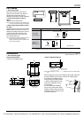
1. Non-voltage input type
For both panel mounting and PC
board mounting types
1) Never apply voltage to the non-voltage
input type. This will damage the internal
elements. Also, since there is a possibility
of erroneous operation, do not connect in
parallel the inputs of a non-voltage input
type and another counter from a single
input signal.
2) Since the current flow is very small
from the count input and reset input
terminals (1 and 3 on the panel
mounting type and terminals e to t and
S to F on the PC board mounting type)
please use relays and switches with high
contact reliability.
3) When inputting with an open collector
of a transistor, use a transistor for small
signals in which ICBO is 1 µA or less and
always input with no voltage.
4) When wiring, try to keep all the input
lines to the count and reset inputs as
short as possible and avoid running them
together with high voltage and power
transmission lines or in a power conduit.
Also, malfunctions might occur if the
floating capacitance of these wires
exceeds 500 pF (10 m 32.808 ft. for
parallel wires of 2 mm
2
). When using 2
kHz mode, use with a wiring floating
capacitance of 120 pF (3 m 9.843 ft. for
parallel wires of 2 mm
2
). In particular,
when using shielded wiring, be careful of
the capacitance between wires.
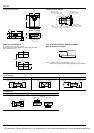
PC board mounting type
1) For external power supply use
manganese dioxide or lithium batteries
(CR type: 3V).
2) Always reset after external power is
applied and confirm that the display
reads “0”.
3) Make the wiring from the battery to the
counter unit as short as absolutely
possible. Also, be careful of polarity.
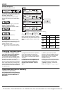
4) Calculate battery life with the following
formula.
t = A/I
t: battery life [h]
I: LC2H current consumption [mA]
A: battery capacity until minimum
operation voltage is reached [mAh]
5) Hand solder to the lead terminal. Do
not dip solder. With the tip of the
soldering iron at 300°C 572°F perform
soldering within 3 seconds (for 30 to 60
W soldering iron).
2. Voltage input type
1) Be aware that applying more than 30 V
DC to count input terminals 1 and 2,
and reset input terminals 3 and 4 will
cause damage to the internal elements.
2) For external resetting use H level
(application of 4.5 to 30 V DC) between
reset terminals 3 and 4 of the rear
terminals. In this case, connect + to
terminal 3 and – to terminal 4. This is
the valid polarity; therefore, the counter
will not work if reversed.
3) When wiring, try to keep all the input
lines to the count and reset inputs as
short as possible and avoid running them
together with high voltage and power
transmission lines or in a power conduit.
Also, malfunctions might occur if the
floating capacitance of these wires
exceeds 500 pF (10 m 32.808 ft. for
parallel wires of 2 mm
2
).
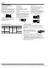
3. Free voltage input type
1) Use count input terminals 1 and 2 for
free voltage input and reset terminals 3
and 4 for non-voltage input.
2) Be aware that the application of
voltage that exceeds the voltage range of
the H level to the count input terminal,
and the application of voltage to the reset
input terminal, can cause damage to the
internal elements.
3) Since the current flow is very small
from reset input terminal 3, please use
relays and switches with high contact
reliability.
4) When inputting a reset with an open
collector of a transistor, use a transistor
for small signals in which ICBO is 1 µA or
less and always input with no voltage.
5) To reset externally, short reset input
terminals 3 and 4 on the rear.
6) Input uses a high impedance circuit;
therefore, erroneous operation may occur
if the influence of induction voltage is
present. If you plan to use wiring for the
input signal that is 10 m or longer (wire
capacitance 120 pF/m at normal
temperature), we recommend the use of
a CR filter or the connection of a bleeder
resistor.
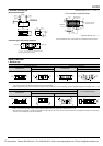
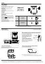
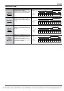
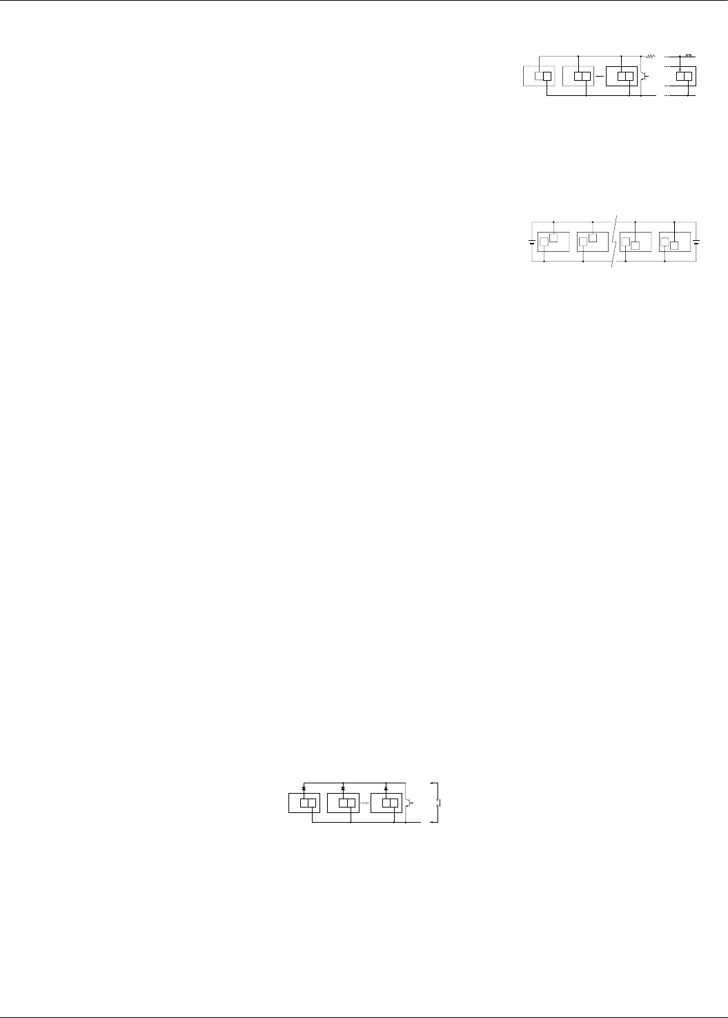
4. How to reset multiple panel
mounting type counters all at once
(input is the same for count)
Non-voltage input type
Notes) 1. Use the following as a guide for choosing
transistors used for input (Tr).
Leakage current < 1 µA
2. Use as small a diode (D) as possible in the
forward voltage so that the voltage between
terminals 3 and 4 during reset input meets
the standard value (0.5 V).
( At IF = 20 µA, forward voltage 0.1 and
higher.)
Voltage input type
Note) Make sure that H (reset ON) level is at least 4.5
V.
5. Backlight luminance
To prevent varying luminance among
backlights when using multiple Backlight
types, please use the same backlight
power supply.
6. Environment for use
1) Ambient conditions
• Overvoltage category II, pollution level 2
• Indoor use
• Acceptable temperature and humidity
range: –10 to +55°C, 35 to 85%RH (with
no condensation at 20°C)
• Under 2000 m elevation
2) Use the main unit in a location that
matches the following conditions.
• There is minimal dust and no corrosive
gas.
• There is no combustible or explosive
gas.
• There is no mechanical vibration or
impacts.
• There is no exposure to direct sunlight.
• Located away from large-volume
electromagnetic switches and power
lines with large electrical currents.
3) Connect a breaker that conforms to
EN60947-1 or EN60947-3 to the voltage
input section.
4) Applied voltage should be protected
with an overcurrent protection device
(example: T 1A, 250 V AC time lag fuse)
that conforms to the EN/IEC standards.
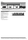
(Free voltage input type)
3
or
D
Tr
4 3 4 3 4
D D
3
or
+V
+V
R
Tr
4 3 4 3 4 3 4
2
2
5
2
Green Red
5
6
2
6
24V DC 24V DC
CTi Automation - Phone: 800.894.0412 - Fax: 208.368.0415 - Web: www.ctiautomation.net - Email: info@ctiautomation.net