


21
Preparation
20
BIf there are any obstacles in between
the remote control unit and the
receivers, the remote control unit may
not operate correctly.
B
If strong light is allowed to shine onto
the remote control signal receiver,
correct remote control operation may
not be possible. Place the projector as
far away from light sources as possible.
BIf facing the remote control unit
toward the screen to operate the
projector, the operating range of the
remote control unit will be limited by
the amount of light reflection loss
caused by the characteristics of the
screen used.
NOTE:
BIf there are any obstacles in between
the remote control unit and the
receivers, the remote control unit may
not operate correctly.
B
If strong light is allowed to shine onto
the remote control signal receiver,
correct remote control operation may
not be possible. Place the projector as
far away from light sources as possible.
BIf facing the remote control unit
toward the screen to operate the
projector, the operating range of the
remote control unit will be limited by
the amount of light reflection loss
caused by the characteristics of the
screen used.
BDo not drop the remote control unit.
BKeep the remote control unit away from liquids.
BRemove the batteries if not using the remote control unit for long periods.
BDo not use rechargeable batteries.
NOTE:
BDo not drop the remote control unit.
BKeep the remote control unit away from liquids.
BRemove the batteries if not using the remote control unit for long periods.
BDo not use rechargeable batteries.
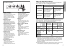
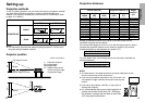
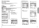
Operating range
If the remote control unit is held so
that it is facing directly in front of the
remote control signal receptors on
the front or rear of the projector, the
operating range is within
approximately 7 m (23´) from the
surfaces of the receptors.
Furthermore, the remote control unit
can be operated from an angle of
±30° to the left or right and ±15°
above or below the receptors.
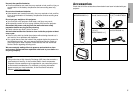
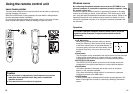
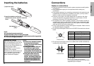
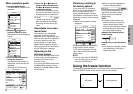
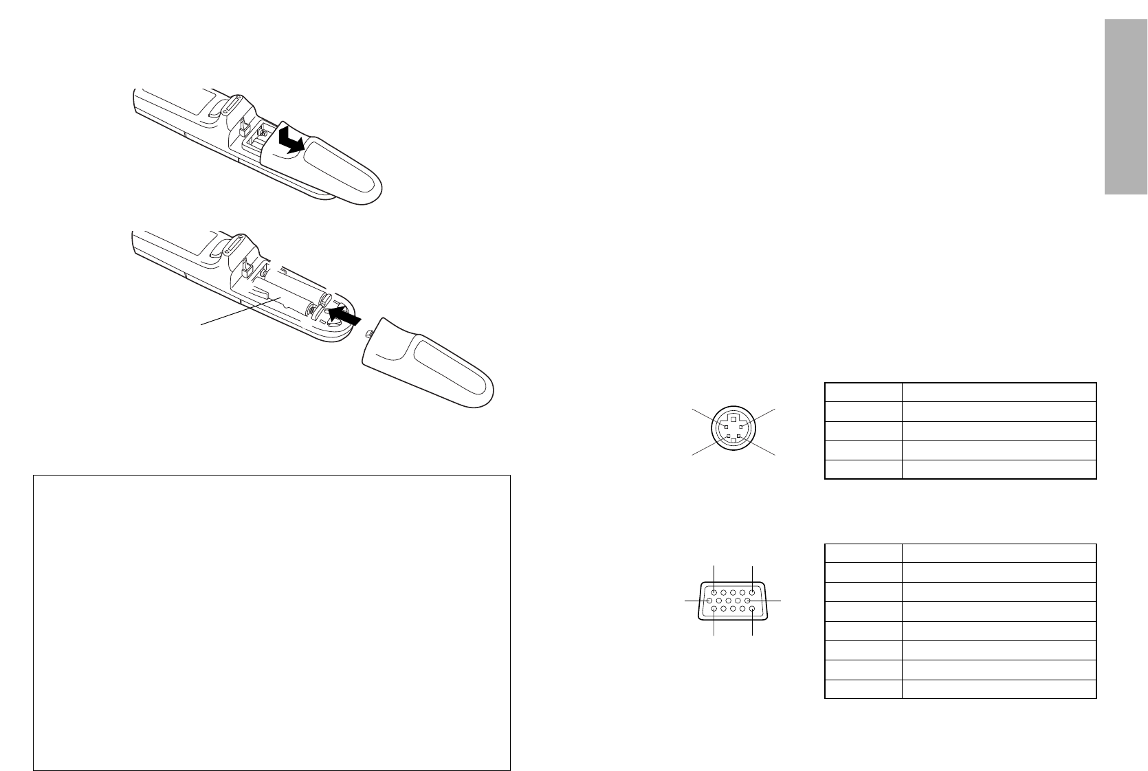
#Open the cover.
AAA batteries
(two)
$Insert the batteries so that the
polarities are correct, and then close the
cover.
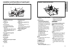
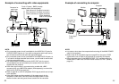
Inserting the batteries Connections
Notes on connections
BRead the instruction manual for each system component carefully before
connecting it.
BTurn off the power supply for all components before making any
connections.
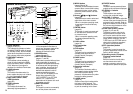
BIf the cables necessary for connecting a component to the system are not
included with the component or available as an option, you may need to
fashion a cable to suit the component concerned.
BIf there is a lot of jitter in the video signal which is input from the video
source, the picture on the screen may flicker. In such cases, it will be
necessary to connect a TBC (time base corrector).
BThe projector has a built-in speaker. However, you will need to connect a
separate audio system to the AUDIO OUT jack if your needs specify high
sound volumes. No sound will come out of the projector’s built-in speaker
while the AUDIO OUT jack is being used.
BIt may not be possible to connect some types of computer. Refer to the list
of compatible signals on page 56.
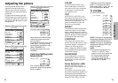
BThe pin layout and signal names for the S-VIDEO IN connector are shown
below.
Pin No. Signal
#
Earth (Luminance signal)
Earth (Color signal)
Luminance signal
Color signal
$
%
&
BThe pin layout and signal names for the RGB/YPBPR (RGB1 IN/RGB2 IN)
connector are shown below.
Pin No. Signal
#
R/P
R
G/G·SYNC/Y
B/P
B
SDA
$
%
.
/
HD/SYNC
0
VD
1
SCL
Pin + is spare.
Pins &–*, , and - are for earth.
Pins . and 1 functions are only valid when
supported by the computer
#$
%&
External view
-1
#'
,(
External view