


111
■ WJ-SX550B Matrix Switcher Control
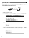
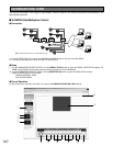
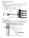
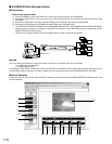
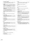
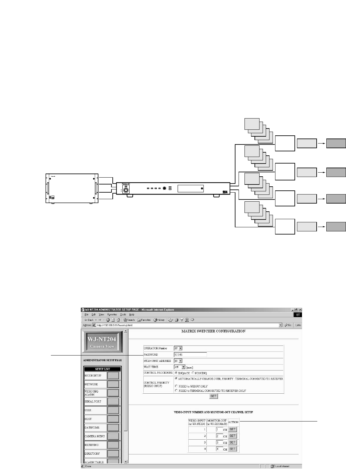
● Connections
(1) Connect the MONITOR OUT connectors on the rear of the WJ-SX550B to the VIDEO IN connectors 1 to 4 on the rear of the
WJ-NT204.
(2) Connect the RS-232C ports (of WJ-SX550B and WJ-NT204) with a RS-232C cable. You can also connect the CONTROL
DATA port on the rear of the WJ-SX550B to the RS-485 connectors on the rear of the WJ-NT204.
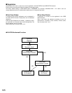
• Random Input Selection Mode
• Unless a user changes channels, the last selected channel is used to continue transmission.
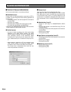
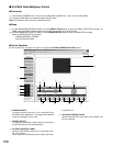
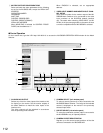
● Setup
Make the CONTROL SETUP as follows.
CAM CONTROL: OTHERS
AUX SYSTEM: SX550A/B
In the SERIAL PORT SETUP window, set TYPE under RS-232C SETUP or RS-485 SETUP to WJ-SX550B. Set the same com-
munication parameters as for the Matrix Switcher. (For further details refer to the operation manual of the WJ-SX550B Matrix
Switcher.) Click the link to [MATRIX SW CONFIGURATION page] at the bottom of the SERIAL PORT SETUP window to open
the MATRIX SWITCHER CONFIGURATION window.
OPERATE
Matrix Switcher WJ-SX550550
1
1
1
1
PC
PC
PC
PC
WJ-NT204
WJ-SX550B
MON1 MON2
MON1 MON2
MON1 MON2
MON1 MON2
Monitor
Out 1
Monitor
Out 2
Monitor
Out 3
Monitor
Out 4
LINK/
10BASE-T
100
BASE-TXCONNECT ACT
LOW HIGH
RING.VOL
Network Interface Unit WJ-NT
POWER
ON
OFF
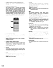
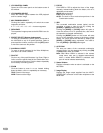
RS-232C
DB25 DB9
8 ...................... 1
3 ...................... 2
2 ...................... 3
20 .................... 4
7 ...................... 5
6 ...................... 6
4 ...................... 7
5 ...................... 8
22 .................... 9
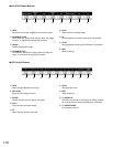
Data Port (WJ-SX550B)
Pin No. Designation
1 Ground
2 R(B)
3 R(A)
4 T(B)
5 T(A)
6 Ground
RS-485
R(B) ............ T(B)
R(A) ............ T(A)
T(B) ............ R(B)
T(A) ............ R(A)
q
w
Note: Set DIP switch #3 on the rear of WJ-NT204 to ON
only when using RS-485 port.