


116
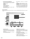
■ WJ-FS309/FS316/FS409/FS416 Video Multiplexer Control
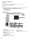
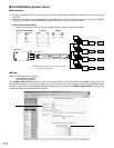
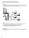
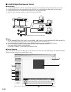
The following description is based on the assumption that a WJ-FS416 is installed in the system.
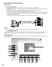
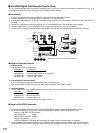
● Connections
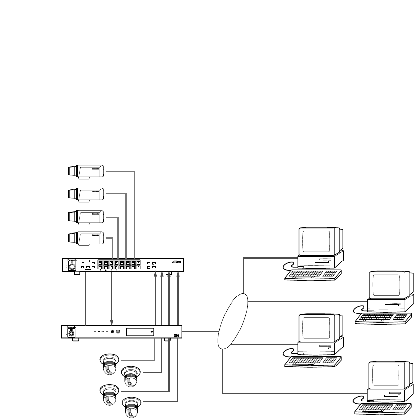
1. Connect ordinary cameras to the video multiplexer while the combination cameras are connected to the WJ-NT204. The
video signals of the combination cameras are supplied to the video multiplexer via the VIDEO OUT 1-4 terminal. Connect
the MULTI SCREEN OUT terminal on the multiplexer to the AUX IN on the WJ-NT204.
2. Connect DATA on the rear of the WJ-FS416 to DATA on the rear of the WJ-NT204 with an RJ-11 type 4-conductor modular
cable.
● Setup
1. On the ADMINISTRATOR SETUP PAGE, click the SERIAL PORT button to open the SERIAL PORT SETUP window. For
TYPE, select PS
•
Data. Set the same communication parameters as for the Video Multiplexer.
2. On the ADMINISTRATOR SETUP PAGE, click the MODE SETUP button to open the MODE SETUP window.
3. Select either H.261 and JPEG in the MAIN PAGE DEFAULT MODE & INDEX FILE SELECT.
Then, select DIRECT COAX for CAM CONTROL and FS309/316/409/416 for AUX SYSTEM CONTROL.
Click the SET & REBOOT. The transmitter WJ-NT204 will restart.
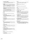
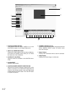
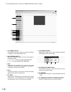
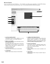
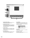
● Control Operation
Type in the location bar http://192.168.0.10/ when you selected JPEG. The 192.168.0.10 in the URL may vary depending on
the WJ-NT204 settings. Type the identical address to that the WJ-NT204 is set to. The VIDEO MULTIPLEXER OPERATION
VIEW window is displayed.
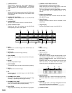
LINK/
10BASE-T
100
BASE-TXCONNECT ACT
LOW HIGH
RING.VOL
Network Interface Unit WJ-NT
POWER
ON
OFF
1
POWER
CAMERA SELECT
SET
ON
OFF
Video Multiplexer WJ-FS
2 3 4 5 6 7 8
9 10 11 12 13 14 15 16
STILL
MENU
ESC
EL-ZOOM
FS
416
VCR
CAM
SPOT
SEQ
MULTISCREEN
MULTI SCREEN
SELECT
ALARM
RESET
ALARM
LAN
DATA
DATA
VIDEO
OUT 1-4
VIDEO
IN 1-4
WJ-FS416
WJ-NT204
PC
PC
PC
PC
MULTI-
SCREEN
OUT
AUX
IN
Note: Set DIP switch #3 on the rear of WJ-NT204 to ON.