


127
■ PS
.
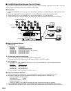
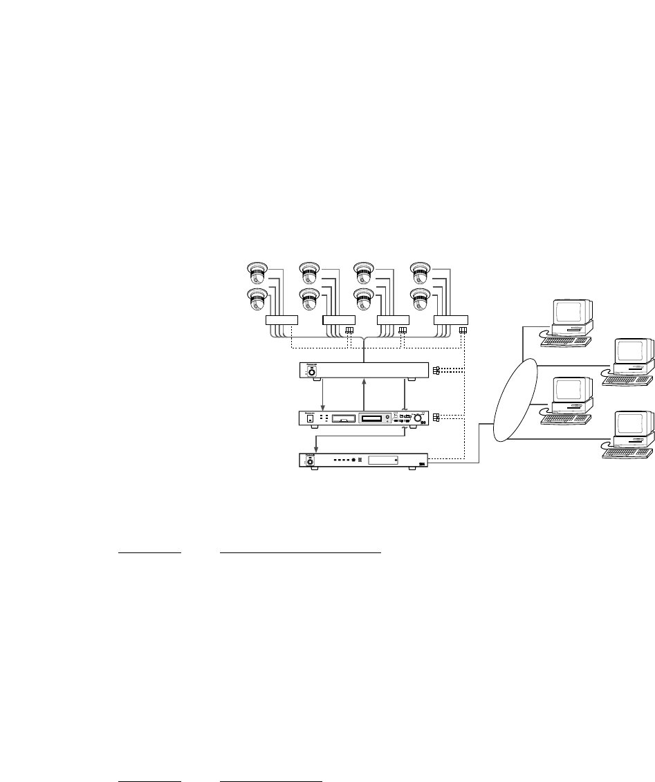
Data System Control (WJ-FS416, WJ-MP204s and WJ-HD100)
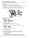
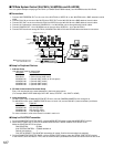
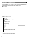
This is a system example employing a WJ-FS416 (or FS409/FS316/FS309 instead), four WJ-MP204 and a WJ-HD100.
● Connections
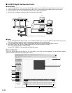
1. Connect MULTISCREEN OUT on the rear of the WJ-FS416 to VIDEO IN on the WJ-NT204 with a BNC attached coaxial
cable.
2. Connect PLAY IN on the rear of the WJ-FS416 to SPOT OUT on the WJ-HD100 with a BNC attached coaxial cable.
3. Connect REC OUT on the rear of the WJ-FS416 to VIDEO IN on the WJ-HD100 with a BNC attached coaxial cable.
4. Connect 16 Combination cameras to CAMERA IN 1-4 on WJ-MP204 unit #1 through #4 with coaxial cables.
5. Connect CAMERA OUT 1-4 on WJ-MP204 unit #1 through #4 to VIDEO IN 1-16 on the WJ-FS416.
6. Connect DATA terminals among WJ-FS416, WJ-MP204 and WJ-HD100 with RS-485 cables and branch connectors.
● Setup for Peripheral Devices
1. Address Setup
Unit addresses must be set as follow.
Unit Name Unit Address
WJ-FS416 1 (set in its own setup menu)
WJ-HD100 2 (set in its own setup menu)
WJ-MP204 #1 3 (set with UNIT switch on its front panel)
WJ-MP204 #2 4 (set with UNIT switch)
WJ-MP204 #3 5 (set with UNIT switch)
WJ-MP204 #4 6 (set with UNIT switch)
2. PS.Data Communication Parameter Setup
Every unit must be set to the same parameter in their own setup menus.
(For example, BAUD RATE: 9600 bps, DATA BIT: 8 bits, STOP BIT: 1 bit, PARITY: NONE)
3. Input Assignment
For WJ-FS-416, open COMMUNICATION SETUP menu, and set CAMERA NUMBER to 001 through 016.
For WJ-MP204 units, open CAMERA CONFIG menu on each unit, and set CAM NO. (camera numbers) as follows.
Unit Name CAM NO.
WJ-MP204 #1 1CH through 4CH
WJ-MP204 #2 5CH through 8CH
WJ-MP204 #3 9CH through 12CH
WJ-MP204 #4 13CH through 16CH
For more information, refer to the manual included in each unit.
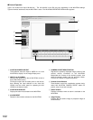
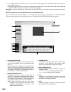
● Setup for WJ-NT204 Transmitter
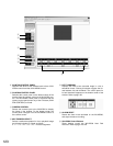
1. On the ADMINISTRATOR SETUP PAGE, click the MODE SETUP button to open the MODE SETUP window.
2. Select either H.323/H.261 or JPEG in the MAIN PAGE DEFAULT MODE & INDEX FILE SELECT area.
Make the CONTROL SETUP as follows.
CAM CONTROL: PS
.
Data
AUX SYSTEM CONTROL: FS309/316/409/416
Default Unit Address: 1
Click SET & REBOOT. The WJ-NT204 transmitter will restart. Confirm the transmitter has restarted.
3. On the ADMINISTRATOR SETUP PAGE, click the SERIAL PORT button to open the SERIAL PORT SETUP window.
In the window, select PS.Data for TYPE, and set communication parameters the same as that other devices are set to.
LINK/
10BASE-T
100
BASE-TXCONNECT ACT
LOW HIGH
RING.VOL
Network Interface Unit WJ-NT
POWER
ON
OFF
LAN
MULTI
OUT
WJ-HD100
WJ-FS416
WJ-NT204
Browser
Browser
Browser
Browser
Ad 6Ad 5Ad 4Ad 3
VIDEO IN 1-16
Ad 1
Ad 2
DATA
DATA
Combination Camera 1-16
WJ-MP204
CAMERA IN 1-4
CAMERA OUT 1-4
POWER
ON
OFF
OPERATE
TIMER HDD
ALARM
SUSPEND
DAYLIGHT
SAVINGS
FULL
LOCK
MEMORY CARD
DISPLAY SELECT
STOP
PLAY REC
PUSH– PAUSE
SET
ALARM SEARCH STEP REW/FF
PLAY MODE SELECT
//
/
/
REC OUT PLAY IN
MONITOR OUT
VIDEO IN
VIDEO IN 1
Note: Set DIP switch #3 on the
rear of WJ-NT204 to ON.