


PANDUIT TDP4*H GMTDPH-MAN
Page 3-1
Printer Dip Switch Configuration
DIP SWITCH PANELS
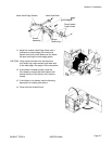
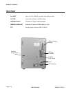
There are two DIP switches (DSW2 and DSW3) located on the front panel under a protective cover. In addition,
a third DIP switch is located on the RS232C Serial Adapter card and is used to set the RS232C transmit/receive
parameters. These switches can be used to set:
• Thermal transfer or direct thermal mode
• Label sensor enable/disable
• Head check mode
• Hex dump mode
• Single Job or Multi-Job Receive buffer
• Operation mode
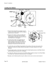
Each switch is an eight section toggle switch. The ON position is always up. To set the switches, first power the
unit Off, then position the DIP switches. Finally, after placing the switches in the desired positions, power the
printer back on. The switch settings are read by the printer electronics during the power up sequence. They will
not become effective until the power is cycled.
RS232 TRANSMIT/RECEIVE SETTING
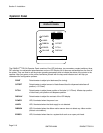
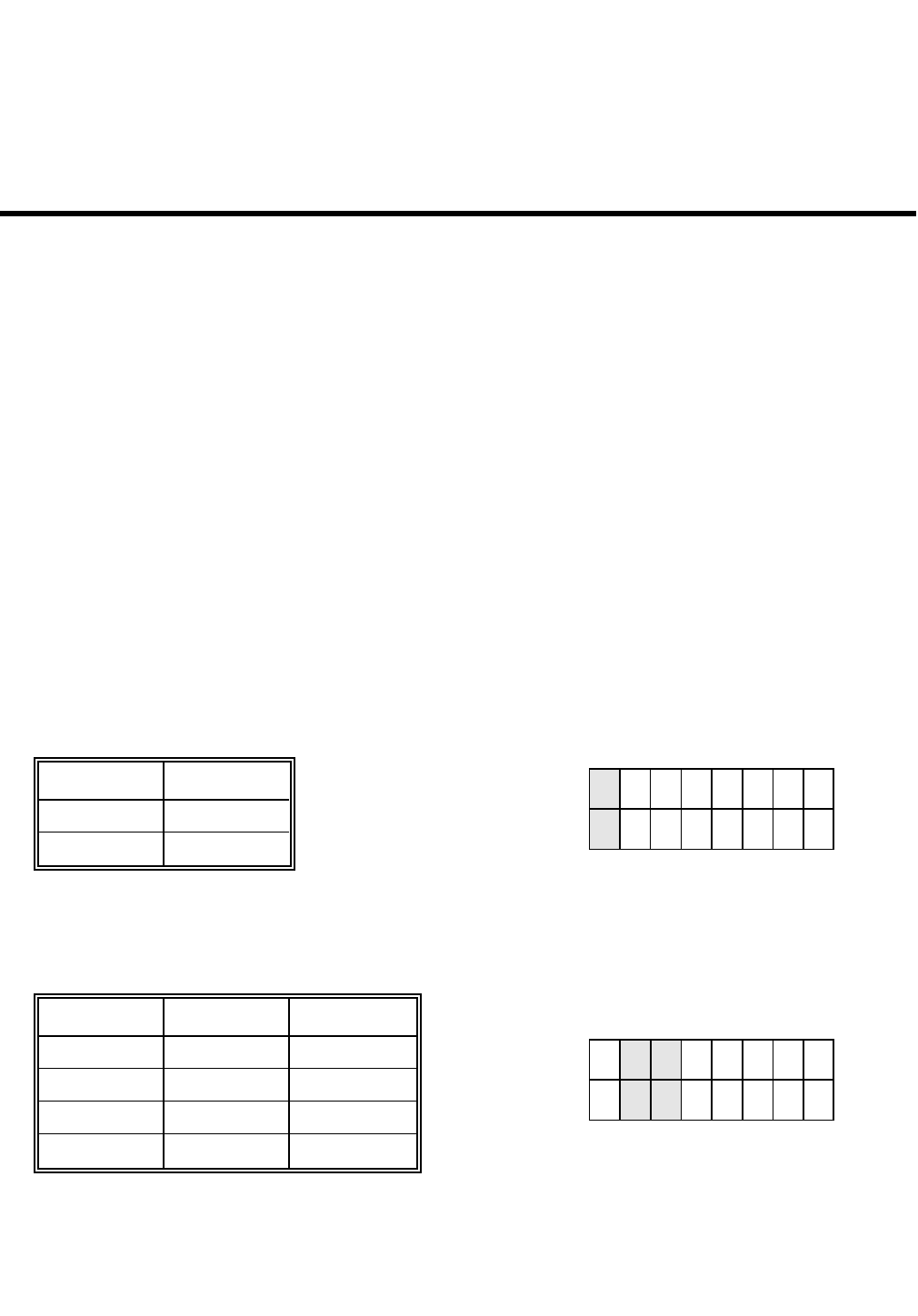
Data Bit Selection (DSW1-1). This switch sets the printer to receive either 7 or 8 bit data bits for each byte
transmitted.
Parity Selection (DSW1-2, DSW1-3). These switches select the type of parity used for error detection.
SECTION 3.
Configuration
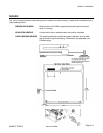
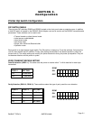
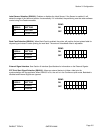
1 2 3 4 5 6 7 8
DSW1
ON
OFF
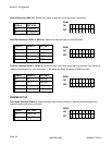
1 2 3 4 5 6 7 8
DSW1
ON
OFF
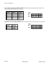
DSW1-1 SETTING
Off 8 Data Bits
On 7 Data Bits
DSW1-1 DSW1-3
Off Off
Off On
SETTING
No Parity
Even
On Off Odd
On On Not Used