


C. Configuration Options
3160-A2-GB24-10 March 2001
C-15
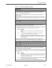
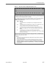
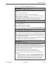
N1 N2 N3 N4 N5 N6 N7 N8 N9 N10 N11 N12 ... N24
Next - - - - - - - - - - - - ... Prev
OR
D1 D2 D3 D4 D5 D6 D7 D8 D9 D10 D11 D12 ... D24
Next - - - - - - - - - - - -- ... Prev
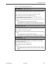
Data Port Channel Allocation (appears for the individual channel method only).
Designates the DS0 channel to allocate to this port, N1–N24 for the network interface and
D1–D24 for the DTE Drop/Insert (DSX-1) interface.
Line 1 displays the 24 channels for the network interface or the DTE Drop/Insert (DSX-1)
interface. Line 2 displays what is allocated to the DS0 channel indicated in Line 1.
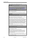
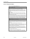
Possible values for Line 2 are:
Value Meaning
– This DS0 channel is not allocated. You can modify this value on this
screen.
Prt
n
This DS0 channel is allocated to port
n,
where
n
is a number from 1 to 4.
You can modify this value on this screen for this port only.
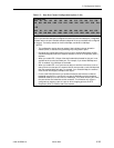
N
n
This DS0 channel is allocated to the network interface DS0 channel
n
,
where
n
is a number from 1 to 24. You cannot modify this value on this
screen.
D
n
This DS0 channel is allocated to the DTE Drop/Insert (DSX-1)
interface DS0 channel
n
, where
n
is a number from 1 to 24. You can modify
this value on this screen.
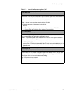
Select the channel by pressing the Function key under that number. To deallocate a port,
press the Function key under that port number. Pressing the Function key under channels
assigned to other ports has no effect.
NOTES:
– The DSU/CSU automatically derives the data rate for the port from the number of
DS0 channels allocated.
– For the 3164 DSU/CSU there is a hardware limitation that limits the combined
bandwidth used by Port 1 and Port 3 to a total of 2048 kbps and the combined
bandwidth used by Port 2 and Port 4 to 2048 kbps. If a selection of Prt
n
causes this
limit to be exceeded, the selection is ignored and the “–” continues to be displayed
for the channel.
Table C-5. Data Port Channel Configuration Options (4 of 4)