


E. Pin Assignments
E-16
March 2001 3160-A2-GB24-10
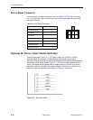
Power Input Connector
The input power connector leads are shown in Table E-10, DC Power Connector.
Pin 1 is at the lower right of the connector and Pin 6 at the upper left as you face
the back of the unit.
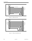
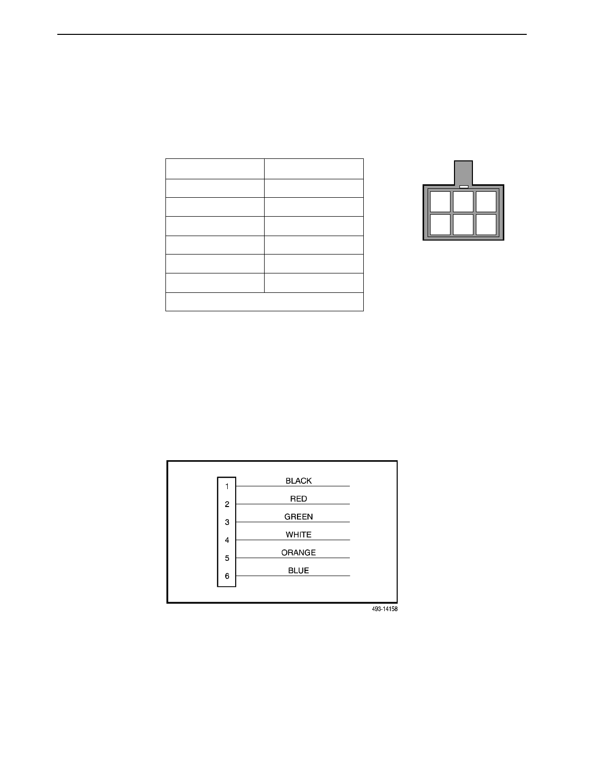
Optional DC Power Cable (Model 3164 Only)
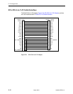
The dc power cable (Figure E-11, DC Power Cable) is a 14.5-foot, 18 AWG
stranded cable. The connector is terminated at one end with a 6-position
connector. The other end of the cable is terminated with a bare wire that should be
connected to a dc power source. Figure E-11, DC Power Cable, shows the wire
colors. The power source can be either a single source of +24 Vdc or up to two
sources of –48 Vdc (A and B). You cannot connect +24 Vdc and –48 Vdc to the
same unit. See the installation instructions in Chapter 2,
Installation
.
Figure E-11. DC Power Cable
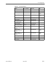
Table E-10. DC Power Connector
Signal Pin Number
–48 Vdc Return* 1, 2
–48 Vdc A* 6
–48 Vdc B* 5
+24 Vdc 5
+24 Vdc Return 4
Chassis Ground 3
* Model 3164 only.
99-16291
23
546
1