


Configuration Options
C-14
3162-A2-GB20-30March 1999
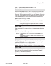
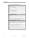
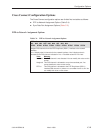
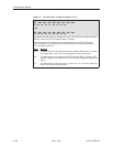
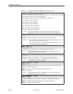
Table C-5. Sync Data Port Assignment Options (3 of 3)
Sync Data Port Assignments
N01 N02 N03 N04 N05 N06 N07 N08 N24
P
n
P
n
P
n
P
n
P
n
P
n
P
n
P
n
P
n
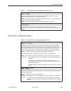
OR
D01 D02 D03 D04 D05 D06 D07 D08 D24
P
n
P
n
P
n
P
n
P
n
P
n
P
n
P
n
P
n
Designates the DS0 channel to allocate to this port, N01–N24 for the network interface
and D01–D24 for the DTE Drop/Insert (DSX-1) interface.
Line 1 displays the 24 channels for the network interface or the DTE Drop/Insert
(DSX-1) interface. Line 2 displays what is allocated to the DS0 channel indicated in
Line 1. Possible values are:
Value
Meaning
N
nn
This DS0 channel is allocated to the network interface DS0 channel
n
, where
n
is a number from 1 to 24. You cannot modify this value on this screen.
D
nn
This DS0 channel is allocated to the DTE Drop/Insert (DSX-1) interface DS0
channel
n
, where
n
is a number from 1 to 24. You can modify this value on this
screen.
P
n
This DS0 channel is allocated to port
n,
where
n
is 1 or 2. You can modify this
value on this screen for this port only.