


Introduction
1-3
3162-A2-GB20-30
March 1999
Physical Description
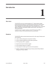
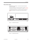
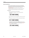
The DSU/CSU front panel (Figure 1-1) contains twelve light-emitting diodes
(LEDs) and six test jacks.
The LEDs are described in the
Front Panel LEDs
section in Chapter 3,
Operation
.
The test jacks are described in the
Test Jacks
section in Chapter 4,
Maintenance
.
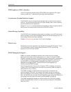
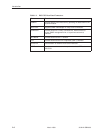
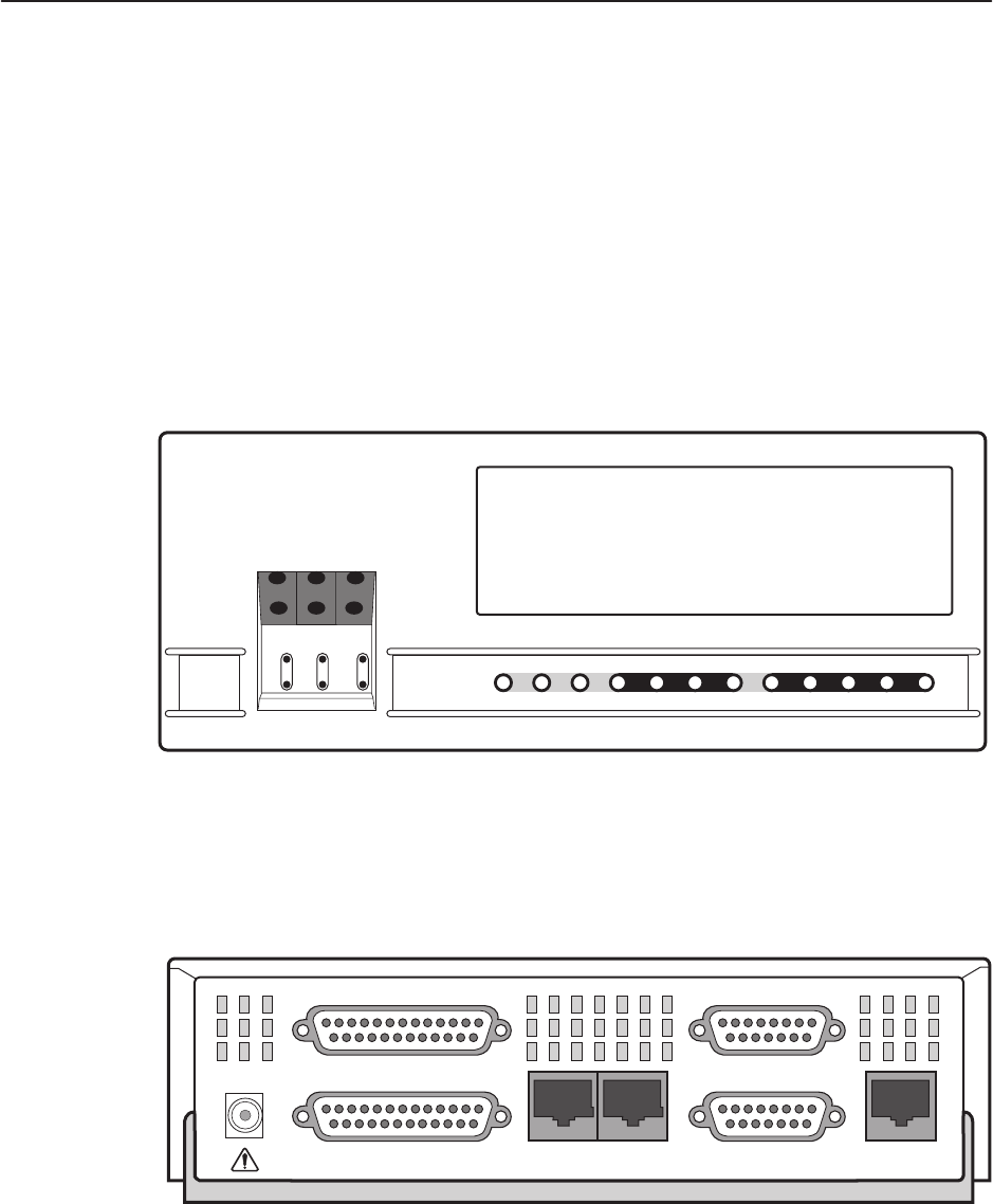
The DSU/CSU rear panel (Figure 1-2) contains the connectors required for the
operation of the DSU/CSU. The connectors and their functions are listed in
Table 1-1.
F1 F2 F3
OK
FAIL TEST SIG OOF ALRM
NETWORK RXD
EER SIG ALRM PDVOOF BPV
3162
ACCULINK
In
Out
In
Out
In
Out
NET
MON EQPT
DTR TXD CTS RTS
496-15001
Figure 1-1. 3162 DSU/CSU Front Panel
496-15002
PORT 1
AUX
POWER
NETWORK
COM
PORT 2
DSX-1
EXT. CLOCK
Figure 1-2. 3162 DSU/CSU Rear Panel