COMSPHERE 3600 Series Data Service Units
4-58 March 1999 3610-A2-GB41-60
Digital Sharing
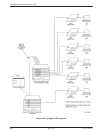
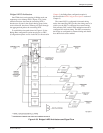
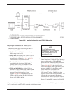
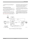
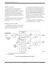
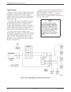
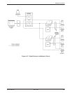
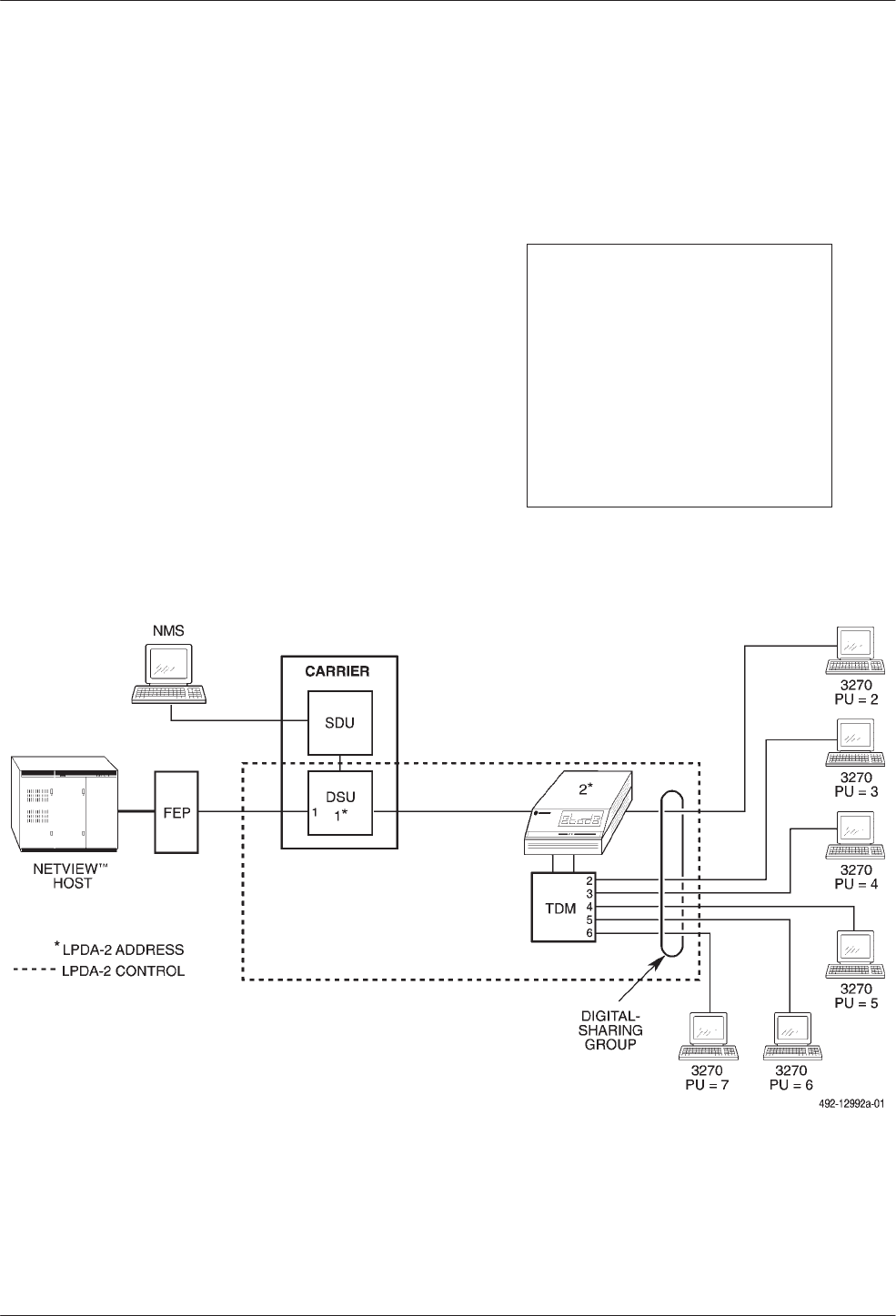
Figures 4-46 and 4-47 show how digital sharing is used
with LPDA-2 monitoring. When a digital-sharing group is
configured on a tributary DSU, the DSU recognizes
multiple LPDA-2 addresses instead of one. The number of
addresses is equal to the number of ports comprising the
digital-sharing group.
The tributary DSU answers to any LPDA-2 command
containing one of the addresses. The DTE connected to
the digital-sharing group must use consecutive PU
addresses. The group must start with Port 1 for the DSU
to support LPDA-2 monitoring on each port of the sharing
group. (A digital-sharing group can be started on any
other port, but it will be ignored by the LPDA-2 protocol.)
From the NetView operator’s perspective, the
digital-sharing feature appears as a unique DSU connected
to each DTE. The LPDA-2 address is set to the lowest PU
address. The DTE with the lowest PU address is then
connected to Port 1. The DTE with the next consecutive
PU address is connected to Port 2 and so on, as shown in
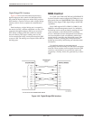
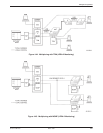
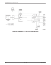
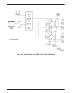
Figures 4-46 through 4-49.
In Figures 4-46 and 4-48, directing a DSU/CSU and
Line Status command to LPDA-2 Address 4 will report
the DTE status of Port 3. In Figures 4-47 and 4-49,
directing a DSU/CSU and Line Status command to
LPDA-2 Address 4 will report the DTE status of Port 2 of
the second tributary DSU.
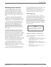
NOTE
For MCMP, a digital-sharing
group is created by assigning
the same channel to each port
in the group. However, for the
SNA Diagnostic Interface option
to recognize the digital-sharing
group, the group must be
specified by the Sharing Device
A (Share DevA) configuration
option.
Figure 4-46. Digital Sharing in a Point-to-Point Circuit


