


Principles of Operation
4-73610-A2-GB41-60 March 1999
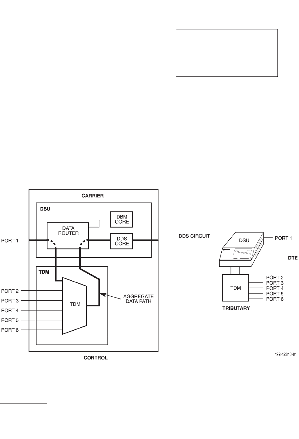
TDM Architecture
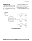
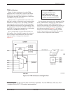
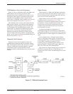
Figure 4-3 shows a high-level view of the TDM
architecture. Port 1 on the DSU is routed to the TDM or
MCMP, where it is multiplexed with Ports 2 through 6.
The aggregate data path of the multiplexer is routed back
to the DDS core* by the data router.
The data router is a sophisticated circuit switch in the
DSU that is capable of connecting several communication
interfaces in a variety of ways. For example, if the DSU
receives an out-of-service network code and is equipped
with a DBM, the data router may be commanded to route
the aggregate data stream from the TDM or MCMP circuit
card to the V.32 core, to be transmitted over a dial backup
connection to the DBM at the tributary site.
Port 1 provides either a physical EIA-232-D/V.24 or
V.35 interface. Ports 2 through 6 comply with a subset of
EIA-232 interface recommendations. The circuit leads
supported on Ports 1 through 6 are discussed in
Appendix C.
NOTE
Throughout this document,
Port 1 refers to either the
EIA-232-D/V.24 or V.35 physical
interface connectors on the DSU.
For non-modular Model 3611 DSUs operating in TDM
mode, a TDM interface (multiplexing) cable attaches to
the multiport connector on the TDM circuit card to
provide fan-out cabling to five individual 25-pin EIA-232
connectors (Ports 2 through 6). The pin assignments for
this cable are provided in Appendix C. For modular
Model 3611 or Model 3610 DSUs operating in TDM
mode, all port connectors are individual and a separate
crossover cable is required for each connector.
Figure 4-3. TDM Architecture and Signal Flow
*A
core
is any module that provides data transmission capabilities. The V.32 DBM has a V.32 core, which
complies with the CCITT V.32 modem recommendation.