


2-13615-A2-GB20-20 December 1996
Installing the Model 3615
DualFlow DSU
Overview 2-1. . . . . . . . . . . . . . . . . . . . . . . . . . . . . . . . . . . . . . . . . . . . . . . . . . . . . . . . . . . . . . . . . . . . . . . . . .
Before you Begin 2-1. . . . . . . . . . . . . . . . . . . . . . . . . . . . . . . . . . . . . . . . . . . . . . . . . . . . . . . . . . . . . . . . . . .
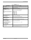
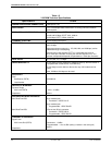
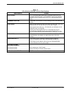
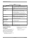
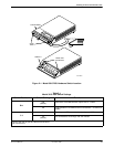
How to Change Hardware Straps 2-2. . . . . . . . . . . . . . . . . . . . . . . . . . . . . . . . . . . . . . . . . . . . . . . . . . . . . . .
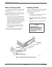
Where to Place the DSU 2-4. . . . . . . . . . . . . . . . . . . . . . . . . . . . . . . . . . . . . . . . . . . . . . . . . . . . . . . . . . . . . .
Installing the DSU 2-4. . . . . . . . . . . . . . . . . . . . . . . . . . . . . . . . . . . . . . . . . . . . . . . . . . . . . . . . . . . . . . . . . . .
Power-up Routine 2-5. . . . . . . . . . . . . . . . . . . . . . . . . . . . . . . . . . . . . . . . . . . . . . . . . . . . . . . . . . . . . . . .
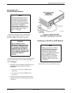
Connecting to the Network 2-5. . . . . . . . . . . . . . . . . . . . . . . . . . . . . . . . . . . . . . . . . . . . . . . . . . . . . . . . . . . .
Connecting to the NMS 2-6. . . . . . . . . . . . . . . . . . . . . . . . . . . . . . . . . . . . . . . . . . . . . . . . . . . . . . . . . . . .
Connecting to the Dial (or PSTN) Network 2-6. . . . . . . . . . . . . . . . . . . . . . . . . . . . . . . . . . . . . . . . . . . .
Connecting to the Switched 56 kbps Network 2-7. . . . . . . . . . . . . . . . . . . . . . . . . . . . . . . . . . . . . . . . . .
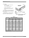
Connecting to the DDS (or LADS) Network 2-7. . . . . . . . . . . . . . . . . . . . . . . . . . . . . . . . . . . . . . . . . . .
Connecting the DSU to a Router 2-9. . . . . . . . . . . . . . . . . . . . . . . . . . . . . . . . . . . . . . . . . . . . . . . . . . . . . . .
Addressing the Unit 2-10. . . . . . . . . . . . . . . . . . . . . . . . . . . . . . . . . . . . . . . . . . . . . . . . . . . . . . . . . . . . . . . . .
Tributary DSU Addressing 2-10. . . . . . . . . . . . . . . . . . . . . . . . . . . . . . . . . . . . . . . . . . . . . . . . . . . . . . . . .
Verifying Operation and Testing Connections 2-10. . . . . . . . . . . . . . . . . . . . . . . . . . . . . . . . . . . . . . . . . . . . .
Verifying DBM Operation 2-11. . . . . . . . . . . . . . . . . . . . . . . . . . . . . . . . . . . . . . . . . . . . . . . . . . . . . . . . . .
Verifying Network Addresses 2-11. . . . . . . . . . . . . . . . . . . . . . . . . . . . . . . . . . . . . . . . . . . . . . . . . . . . . . .
Verifying the Network 2-12. . . . . . . . . . . . . . . . . . . . . . . . . . . . . . . . . . . . . . . . . . . . . . . . . . . . . . . . . . . . .
Other Tests 2-12. . . . . . . . . . . . . . . . . . . . . . . . . . . . . . . . . . . . . . . . . . . . . . . . . . . . . . . . . . . . . . . . . . . . . .
Overview
The Model 3615 DualFlow DSU is designed for
desktop operation and is delivered ready to connect to the
network. It is configured as a tributary DSU for operation
at 56 kbps on a point-to-point circuit.
Installation consists of the following steps, which
should be performed in the order listed.
•
Physical installation
•
Hardware straps
• Electrical connection
• Network diagnostic connection
• Software configuration
• DDS network (or LADS) connection
• Dial network (or PSTN) connection
• Router connection
• Verification testing
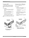
Although the Model 3615 DualFlow DSU is designed
for desk or table-top operation, you can order an
ACCULINKr 3100 Series CSU wall-mount adapter if
you want to mount the DSU on a wall, an equipment
shelf, a 19-inch RS-310-C or 23-inch AT&T
DATAPHONEr equipment cabinet. Refer to Appendix F
to order the adapter.
Before
Y
ou Begin
Your
installation site should be clean, well-lighted,
well-ventilated, and free from environmental extremes.
A dedicated grounded ac outlet that is protected by a
circuit breaker should be installed within 6 feet of the
DSU’s planned location. The outlet should be capable of
supplying 90 to 132 Vac 60 Hz (U.S. and Canada). At the
branch site, the circuit must be capable of supplying a
minimum of 2 amperes at 115 Vac. Refer to the Technical
Specifications section in Chapter 1 for additional power
requirements.
2