


Installing the Model 3616 DualFlow DSU
3-93615-A2-GB20-20 December 1996
Connecting to the
DDS (or LADS) Network
NOTE
Before connecting the DSU to
the DDS network, ensure that
approved primary protectors
have been installed on the
circuit in accordance with Article
800 of the National Electric
Code, NFPA 70, in the United
States and Section 60 of the
Canadian Electric Code, Part 1,
in Canada.
If connecting the DSU to a LADS network there are
distance limitations that govern the use of DSUs on the
network. T
able 2-2 in Chapter 2 summarizes these
limitations.
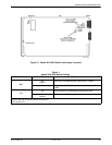
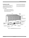
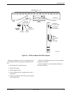
The DDS network interface is provided by two RJ48T
50-pin connectors on the back of the carrier (refer back to
Figure 3-2, DDS Interface). Each connector serves eight
contiguous slots in the carrier: one for Slots 1 through 8
and one for Slots 9 through 16.
Appendix E provides connectivity diagrams should you
need further assistance in connecting the DSU to the
network.
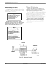
Connecting the DSU
to a Router
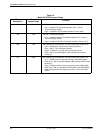
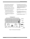
The rear connector plate provides the router interface
for the Model 3616 DSU. Each rear connector plate
contains two DB25 (or 25-pin D-type) connectors. The
top connector is an EIA-232-D/V.24 (ISO 2110)
connector. The bottom connector is a CCITT V.35
(ISO 2593) connector.
For the 25-pin V.35 connector
, use a V
.35 Interconnect
Cable (feature number 3000-F1-510). This cable provides
the interface between the 25-pin V.35 D-type connector
and a V
.35 router cable.
Appendix E provides connectivity diagrams should you
need further assistance.
The DualFlow DSU transmits user data through its
V.35 interface, and diagnostic or user data through its
EIA-232-D/V
.24 interface. Cabling is based upon the
preset configuration (SyBC, SyBT, or DiDg) selected in
the Opts subbranch (Config branch).
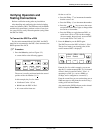
. Procedure
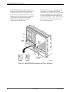
1. Install the V
.35 Interconnect Cable as described in
Step 8 of the Installing the DSU
section of this
chapter.
2. Connect the plug end of the router’
s V
.35 cable to
the DSU’
s V
.35 connector.
T
ighten the two holding screws.
3. Connect the other end of the router’
s V
.35 cable to
the router’s primary serial port.
T
ighten any holding screws.
4. Connect the plug end of the router’s EIA-232
cable to the DSU’s EIA-232-D/V.24 connector.
T
ighten any holding screws.
5. Connect the other end of the router’s EIA-232
cable to the router:
•
If the DSU is to be configur
ed using the SyBC
or SyBT configuration, connect to the router’s
secondary serial port.
•
If the DSU is to be configur
ed using the
DiDg
configuration, connect to the router’
s console
port.
T
ighten any holding screws.