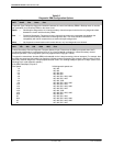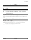
COMSPHERE DualFlow Data Service Units
5-14 December 1996 3615-A2-GB20-20
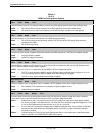
Table 5-4
(2 of 3)
DBM Port Configuration Options
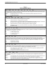
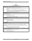
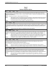
DSR FrcOn: Enab
Next Enab Disab Prev
Data Set Ready Forced On
. Provides the ability to override any other options controlling the Data Set Ready lead.
Enab — DSR remains ON as long as the device is working regardless of tests and network alarms.
Disab — DSR functions as an active lead reflecting various test and alarm conditions and other options.
DSR on Tst: Enab
Next Enab Disab Prev
Data Set Ready On in Test
. Controls the behavior of the DSR lead during testing.
Enab — DSR is ON continuously during testing, allowing a DTE that relies on DSR being ON to send test
messages to the DBM.
Disab — DSR is Off during testing.
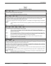
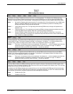
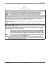
RespondRDL: Disab
Next Enab Disab Prev
Respond to Remote Digital Loopback
. Determines whether the DBM responds to a V.54 Remote Loopback request.
Enab — Performs a Digital Loopback.
Disab — Ignores the Loopback command.
RL by DTE: Disab
Next Enab Disab Prev
Remote Digital Loopback by DTE
. Allows Pin 21 of the EIA-232-D/V.24 interface or Pin N of the V.35 interface by the
DTE or router to initiate a Remote Digital Loopback.
NOTE: Use of Pin 18 or Pin L is determined by the DBM’s
DTE Port
configuration option.
Enab — The DTE or router forces the DBM to request a Remote Digital Loopback when the signal on Pin 21 or
Pin N is turned ON. Remote Digital Loopback ends when the signal is dropped.
Disab — The DTE or router cannot initiate Remote Digital Loopback.
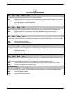
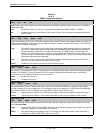
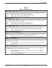
Bilat Lpbk: Disab
Next Enab Disab Prev
Bilateral Loopback
. If this configuration option is enabled, a DTE Loopback occurs when a Digital Loopback occurs.
Enab — When enabled, DTE Loopback occurs whenever a Digital Loopback occurs.
Disab — Disables Bilateral Loopback.
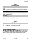
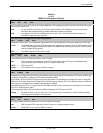
Ext Leads: Rate
Next ExtLd Rate RPowr Prev
External Leads
. Controls the general-purpose leads on the EIA-232-D/V.24 interface except when Rate is selected.
These leads can be controlled and monitored from the DCP or a 6700 or 6800 Series NMS.
ExtLd — Enables Pins 12 and 13 as output (control) and Pins 19 and 23 as input (alarm) leads. When enabled,
Pins 12 and 13 output +12V when ON and –12V when Off. Pins 19 and 23 recognize voltages from +2.2V
to +12V as ON (reported as an External alarm) and –12V to +.8V as Off.
Rate — Pin 12 on the port is turned Off to indicate that the DBM is in fallback mode. If the port does not fall back
and remain at the same speed, then the fallback feature in the DCE or router connected to that port
should not be enabled.
RPowr — Functions similarly to ExtLd, but the inputs report power failure or fan alarms when a redundant power
supply is installed in the COMSPHEREr 3000 Series Carrier.


