Installing the Model 3615 DualFlow DSU
2-93615-A2-GB20-20 December 1996
Connecting the DSU
to a Router
The DualFlow DSU transmits user data through its
V.35 interface and diagnostic or user data through its
EIA-232-D/V
.24 interface. Cabling is based upon the
preset configuration (SyBC, SyBT, or DiDg) selected in
the Opts subbranch (Config branch).
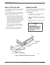
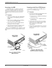
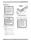
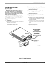
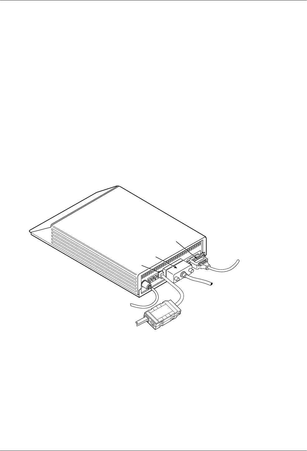
Figure 2-7 shows the DualFlow DSU’s rear panel.
Refer to this figure as you connect the DSU to the router.
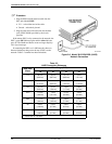
Appendix E shows examples common to the DSU-to-
router application configurations.
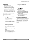
. Procedure
1. Connect the plug end of the router’
s V
.35 cable to
the DSU’
s V
.35 connector.
T
ighten the two holding screws.
2. Connect the other end of the router’
s V
.35 cable to
the router’s primary serial port.
T
ighten any holding screws.
3. Connect the plug end of the router’s EIA-232
cable to the DSU’s EIA-232-D/V.24 connector.
T
ighten any holding screws.
4. Connect the other end of the router’s EIA-232
cable to the router:
•
If the DSU is to be configur
ed using the SyBC
or SyBT configuration, connect to the router’s
secondary serial port.
•
If the DSU is to be configur
ed using the
DiDg
configuration, connect to the router’
s console
port.
T
ighten any holding screws.
496-14498-01
EIA-232-D/V.24
INTERFACE
V.35
INTERFACE
DiDg CONFIGURATION:
TO ROUTER
CONSOLE PORT
(ROUTER-MANAGEMENT
DATA)
DSU
LOW
VOLTAGE
AC POWER
IN
TO ROUTER
PRIMARY SERIAL PORT
(USER DATA)
TO NMS
(CONTROL
DEVICE
ONLY)
CC
SyBC OR SyBT
CONFIGURATION:
TO ROUTER
SECONDARY SERIAL PORT
(BACKUP OR OVERFLOW
DATA)
3000HUBBING DEVICE
MODEL #3000-F3-300
Figure 2-7. Router Connection


