


2. Model 3830 Modem Installation
2-53830-A2-GB91-30 August 1998
2-Wire Leased-Line Connection
Use the following procedures to connect a Model 3830 modem to the
6-pin, center pair, leased-line network interface. (For 2-wire leased line
connection to a JM8 network interface, refer to Appendix C, Pin
Assignments.)
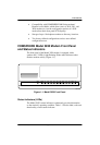
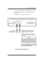
1. Insert the 6-position, 4-conductor modular plug into the jack
labeled LINE, Figure 2-1.
2. Insert the other end of the modular cord into the leased-line
network interface.
Telephone Connection
Use the following procedures to connect the modem to a telephone:
1. Insert the 6-position, 4-conductor modular plug into the jack
labeled PHONE.
2. Insert the other end of the modular cord into the telephone.
AC Power Transformer Connection
Use the following procedures to connect the modem to an ac power
outlet:
1. Make sure the modem’s power switch is in the Off position.
2. Insert the power transformer’s 5-pin DIN male connector into the
modem’s rear panel ac power receptacle (Figure 2-1).
3. For the 115V power transformer, insert the power transformer into
a grounded ac power outlet.
For the 220–240V power transformer, insert the line cord’s outlet
connector into the power transformer’s IEC 320 power outlet.
Next, insert the line cord wall plug into the appropriate grounded
ac outlet.