


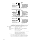
; input 1 on I/O brick 1
NTRATE50 ; Set the broadcasting rate to 50 milliseconds
Third 6K or Gem6K:
NTRATE50 ; Set the broadcasting rate to 50 milliseconds
; This third unit will receive data only. Therefore, it does not require
; a unit ID number or VARSHO data assignment
Program
Interaction
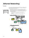
Each Unit can read the broadcast variables of each other unit with the
nVARSHIi
command.
The “
n
” specifies the ID number (
NTID
) of the unit you want to read from, the “
i
” is the
VARSHO
number of that unit to be read. For example, if you want unit 1 to read unit 2’s
VARSHO8
data, then use
2VARSHI8
.
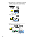
Using the
VARSHI
command, you can process data from the
VARSHO
variable of another peer-
to-peer unit. Use the following ways:
• Assign the
VARSHO
data to a
VAR
(numeric),
VARI
(integer), or
VARB
(binary) variable.
For example, the command
VARI1=2VARSHI8
assigns the value of
VARSHO8
on unit 2
to the
VARI1
integer variable.
• Assign the VARSHO
data to a virtual input (
IN
). For example,
3IN=2VARSHI3
assigns
the binary value of
VARSHO3
from unit 2 to virtual input brick 3.
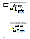
• Use the
VARSHO
data in a conditional expression for an
IF
,
WAIT
,
WHILE
, or
UNTIL
statement. For example, if
VARSHO5
on unit 2 is assigned is assigned the status of
onboard trigger input 3 (
VARSHO5=IN.3
), then you could use this command to make
unit 1 wait until trigger input 3 on unit 2 was on:
WAIT(2VARSHI5=b1)
.
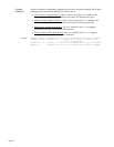
Example
First 6K or Gem6K (unit 1):
VARI1 = 2VARSHI8 ; Assign Unit 2's VARSHO8 (which is the voltage value
; at analog input 1 on I/O brick 1) to VARI1.
Second 6K or Gem6K (unit 2):
VARI100 = 1VARSHI2 ; Assign Unit 1's VARSHO2 (which is the encoder position
; of axis 1) to VARI100.
Third 6K or Gem6K (reading data only):
VARI90 = 1VARSHI1 ; Assign Unit 1's VARSHO1 (which is the acceleration of
; axis 1) to VARI90.
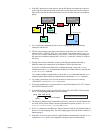
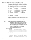
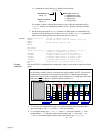
Networking with OPTO22 SNAP I/O
The 6K client can communicate with the OPTO22 SNAP I/O server to read digital and analog
inputs and outputs, and write digital and analog outputs. The 6K supports up to eight modules
per OPTO22.
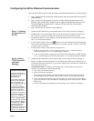
Setup
1. Follow the manufacturer’s setup procedure for the OPTO22 Ethernet I/O rack.
2. Connect the 6K and OPTO22 products in a network and configure the 6K for Ethernet
communication according to the procedures on page 4.
3. Choose a Server Connection Number for this device. The 6K can support up to 6
simultaneous server connections. Pick a number (1-6) that has not been used already for
another connection. This will be used to reference the OPTO22 unit from now on.
4. Enter the IP address of the OPTO22 and specify a 2 for connection type with the
NTIP
command. For example, if the OPTO22 is Server #3 and its IP address is 172.20.34.170,
then the command would be
3NTIP2,172,20,34,170
.
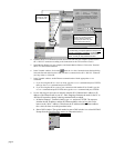
5. Attempt a connection to the device with
NTCONN
. For example, if the server number is 3,
the command would be
3NTCONN1
. If the connection is successful, Network Status bit #1
is set (see
NTS
,
TNTS
,
TNTSF
). If the connection is unsuccessful, Error Status bit #23 is
set (see
ER
,
TER
,
TERF
).
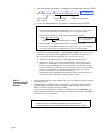
6. Inform the 6K of the configuration of the OPTO22. For each module position, use the
page 9