


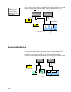
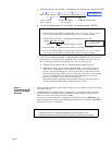
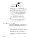
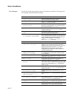
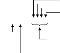
n
\
m
OUT
b
b
b
b
Module # on Server “n”
Range: 0-7
Network Server #
Range: 1-6
Options for “
b
” are:
1 = Turn on
0 = Turn off
x = Don’t Change
O
u
t
pu
t
#1
Output #2
Output #3
Output #4
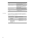
For example (Server #3), to turn on outputs #1 and #4 and leave outputs #2 and #3 un-
changed on module #2, type
3\2OUT1XX1
. To turn off only output #4, type
3\2OUT.4-0
.
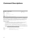
• To set an analog output voltage, type
n\mANO.i-r
, where “
n
” is the server number, “
m
” is
the module number, “
i
” is the output number on that module and “
r
” is the voltage. For
example, to set analog output #1 on module #5 of Server #3 to 6.4V, type
3\5ANO.1=6.4
.
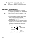
• To read a digital input or output module, use the assignment/comparison operands (
n\mIN
or
n\mOUT
) or the transfer commands (
n\mTIN
or
n\mTOUT
). Following are examples:
- IF(3\0IN=b1100) is an IF condition that reads all four digital inputs on module #0.
IF(3\0IN.2=b1) is an IF condition that reads only digital input #2 on module #0.
- IF(3\2OUT=b1100) is an IF condition that reads all four outputs on module #2.
IF(3\2OUT.3=b1) is an IF condition that reads only digital output #3 on module #2.
- 3\0TIN transfers the binary status of all four digital inputs on module #0.
3\0TIN.2 transfers the binary status of only digital input #2 on module #0.
- 3\2TOUT transfers the binary status of all four digital outputs on module #2.
3\2TOUT.3 transfers the binary status of only digital output #3 on module #2.
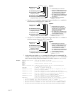
• To read an analog input or output module, use the assignment/comparison operands
(
n\mANI
or
n\mANO
) or the transfer commands (
n\mTANI
or
n\mTANO
). Following are
examples:
- WAIT(3\7ANI.2<2.4) is an WAIT condition that reads analog input #2 on module #7.
- IF(3\5ANO.1>=1.0) is an IF condition that reads analog output #1 on module #5.
- 3\6TANI transfers the voltage status of both analog inputs on module #6.
3\6TANI.2 transfers the voltage status of only analog input #2 on module #6.
- 3\4TANO transfers the voltage status of both analog outputs on module #4.
3\4TANO.1 transfers the voltage status of only analog output #1 on module #4.
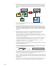
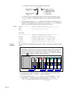
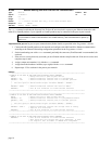
Networking with a DVT Vision System
The controller can send trigger commands to the camera. The camera should send back ASCII
strings similar to what follows:
VARn = 123.456, VARm = 234.567
. The ASCII strings are
VAR
assignments set apart by commas. The values are then written to the controller’s
VAR
s;
This data can represent anything, such as an x-y coordinate.
Setup
1. Follow the manufacturer’s setup procedure for the DVT camera.
2. Connect the 6K and DVT camera in a network and configure the 6K for Ethernet
communication according to the procedures on page 4.
3. Choose a Server Connection Number for this device. The 6K can support up to 6
simultaneous client connections. Pick a number (1-6) that has not been used already for
another server connection. This will be used to reference the device from now on.
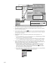
4. Enter the IP address of the camera and specify a 3 for connection type with the
NTIP
command. For example, if the DVT camera is Server #6 and its IP address is
172.20.34.150, then the command would be
6NTIP3,172,20,34,150
.
5. Attempt a connection to the device with
NTCONN
. For example, if the server number is 6,
the command would be
6NTCONN1
. If the connection is successful, Network Status bit
#1 is set (see
NTS
,
TNTS
,
TNTSF
). If the connection is unsuccessful, Error Status bit #23
is set (see
ER
,
TER
,
TERF
).
page 11