


[ \ANO ]
Network Analog Output Status
Type:
Network; Assignment or Comparison
Product Rev
Syntax:
n\mANO.i (see example below)
Units:
n = network server #
m = module #
i = analog output # on module “m”
Range:
n = 1-6
m = 0-7
j = 1-2
Default:
n/a
Response:
n/a
See Also:
\ANO, NTIO, \TANI, \TIO, VAR
6K 5.3
Use the
\ANO
operand to assign the voltage level of an OPTO22 analog output to a real variable (
VAR
), or to make a
comparison against another value. The voltage at the analog outputs is controlled with the
\ANO
command.
Syntax:
VARx=n\mANO.i
where “
n
” is the network server number of the OPTO22 unit, “
m
” is the I/O module number,
and “
i
” is the output/channel number on the module (e.g.,
VAR3=2\5ANO.1
assigns the voltage at analog input 1
on module 5 of OPTO22 server 2 to
VAR3
). The
\ANO
operand can also be used in a condition expression such as
IF(2\3ANO.1>=2.0)
or
WAIT(2\4ANO.1<=1.5)
.
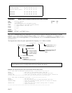
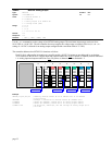
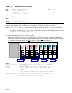
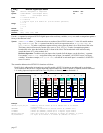
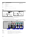
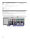
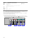
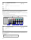
The controller addresses the OPTO22 I/O locations as follows:
Each I/O bit is addressed by its location on a specific module. (NOTE: I/O points are not addressed by an absolute
32-bit location on the OPTO22.) Digital input and output modules have four I/O points, or channels, and are numbered
1-4. Analog input and output modules have two I/O points, or channels, and are numbered 1-2.
Digital
Input
Module
Input
1
0
Input
2
Input
3
Input
4
Digital
Input
Module
Input
1
1
Input
2
Input
3
Input
4
Digital
Output
Module
Output
1
2
Output
2
Output
3
Output
4
Digital
Output
Module
Output
1
3
Output
2
Output
3
Output
4
Analog
Output
Module
Output
1
4
Output
2
Analog
Output
Module
Output
1
5
Output
2
Analog
Input
Module
Input
1
6
Input
2
Analog
Input
Module
Input
1
7
Input
2
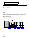
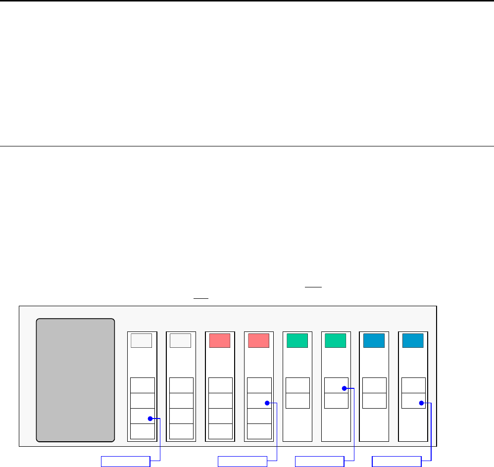
EXAMPLE: OPTO22 is Network Server #2
2\0IN.3 2\3OUT.2 2\5ANO.1 2\7ANI.2
Example:
2NTIP2,172,54,125,34 ; Identify network server #2 as an OPTO22 unit at IP address
; 172.54.125.34
2NTCONN1 ; Attempt a connection to network server #2 (OPTO22 unit)
2\4NTIO4 ; Server #2 (OPTO22), module #4 is an analog output module
2\4ANO.1=4.8 ; On Server #3, module #4, set the voltage on analog output #1 to
; +4.8 VDC
VAR23=2\4ANO.1 ; Assign the voltage at analog output #1 on module #4 of Server #2
; to real variable #23 (VAR23). Based on the preceding command,
; the value should be +4.80.
WAIT(2\4ANO.2<=+1.5) ; Wait until the voltage at analog output #1 of module #4 on
; Server #2 is less than or equal to +1.5VDC
page 36