


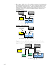
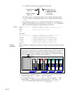

NTIO
command to specify the type of module in that position.
n
\
m
NTIO
<i>
Module # on Server “n”
Range: 0-7
Network Server #
Range: 1-6
Module Type. Options are:
1 = Digital/Discrete Inputs
2 = Digital/Discrete Outputs
3 = Analog Inputs
4 = Analog Outputs
For example, if there is a digital input module in slot 0, then the command would be
3\0NTIO1
. If there is an Analog Input module in slot 7, then the command would be
3\7NTIO3
.
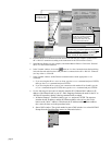
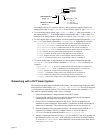
7. Set the polling rate with the
NTPOLL
command. 50 milliseconds is recommended. For
example, to set the polling rate to 50 ms on server #3, use the
3NTPOLL50
command. If
there is an error during polling, then Error Status bit #24 will be set.
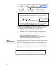
Example
NTADDR172,34,54,123 ; Set the IP address of the 6K
OPTEN0 ; Disable the option card (for Fieldbus units only)
RESET
NTFEN2 ; Enable network function on 6K
RESET
DEL OPTOSU
DEF OPTOSU
2NTIP2,172,34,54,124 ; Identify an OPTO22 device as Server #2, which is
; located at IP address 172.34.54.124
2NTCONN1 ; Attempt connection to Server #2 (OPTO22)
2\1NTIO2 ; Configure OPTO22 module 1 as digital output
2\2NTIO2 ; Configure OPTO22 module 2 as digital output
2\3NTIO1 ; Configure OPTO22 module 3 as digital input
2\4NTIO3 ; Configure OPTO22 module 4 as analog input
2NTPOLL50 ; Begin polling, set polling interval to 50 ms
END
Program
Interaction
Once the OPTO22 is configured and a connection is made, you can then set outputs and check
inputs.
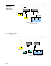
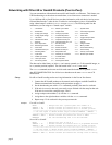
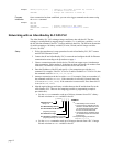
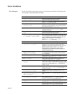
How the 6K addresses OPTO22 I/O locations:
The 6K addresses each I/O bit by its location on a specific module. (NOTE: I/O points are
not addressed by an absolute 32-bit location on the OPTO22.) Digital input and output
modules have four I/O points, or channels, and are numbered 1-4. Analog input and output
modules have two I/O points, or channels, and are numbered 1-2.
Digital
Input
Module
Input
1
0
Input
2
Input
3
Input
4
Digital
Input
Module
Input
1
1
Input
2
Input
3
Input
4
Digital
Output
Module
Output
1
2
Output
2
Output
3
Output
4
Digital
Output
Module
Output
1
3
Output
2
Output
3
Output
4
Analog
Output
Module
Output
1
4
Output
2
Analog
Output
Module
Output
1
5
Output
2
Analog
Input
Module
Input
1
6
Input
2
Analog
Input
Module
Input
1
7
Input
2
EXAMPLE: OPTO22 is Network Server #3
3\0IN.3 3\3OUT.2 3\5ANO.1 3\7ANI.2
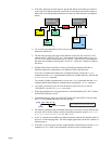
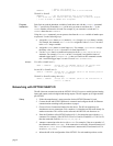
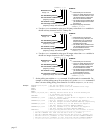
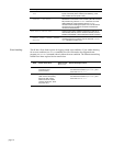
• To verify the I/O configuration (as per
NTIO
) and to check the status of each module’s
inputs and outputs, type
n\TIO
, where “
n
” is the server number.
• To set a digital output, type
n\mOUT.i-b
, where “
n
” is the server number, “
m
” is the
module number, “
i
” is the point number on that module and “
b
” is the state (
1
= on,
0
= off). To set multiple digital outputs on the same module, type
n\mOUTbbbb
:
Ot t#1
page 10