


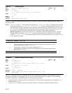


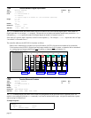
* 1 DIGITAL OUTPUTS 0001
* 2 ANALOG OUTPUTS +10.000, -4.456
* 4 DIGITAL INPUTS 1110
* 7 ANALOG INPUTS +6.753, +0.000
\TOUT
Transfer Network Digital Output Status
Type:
Network; Transfer
Product Rev
Syntax:
<!>n\mTOUT<.i>
Units:
n = network server #
m = module #
i = digital output # on module “m” (for bit-select operation)
Range:
n = 1-6
m = 0-7
i = 1-4
Default:
n/a
Response:
1\1TOUT:
1\1TOUT.2:
*1100
*1
See Also:
[ \OUT ], NTIO, \TIO
6K 5.3
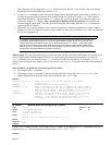
The
\TOUT
command returns the current status (active/on or inactive/off) of the OPTO22 digital outputs (the outputs are
turned on and off with the
\OUT
command). Each module of digital outputs has its own unique
\TOUT
response. The
network server number and module number must precede the
\TOUT
command (e.g.,
2\3TOUT
reports the status of all
digital outputs on module 3 of network server 2).
If the status of a specific output is required, use the bit select operator (
.
). For example,
1\3TOUT.2
reports the status of
output 2 on module 3 of network server 1.
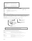
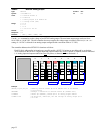
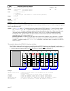
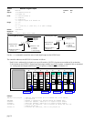
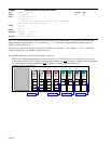
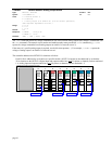
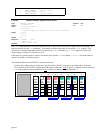
The controller addresses the OPTO22 I/O locations as follows:
Each I/O bit is addressed by its location on a specific module. (NOTE: I/O points are not addressed by an absolute
32-bit location on the OPTO22.) Digital input and output modules have four
I/O points, or channels, and are numbered
1-4. Analog input and output modules have two
I/O points, or channels, and are numbered 1-2.
Digital
Input
Module
Input
1
0
Input
2
Input
3
Input
4
Digital
Input
Module
Input
1
1
Input
2
Input
3
Input
4
Digital
Output
Module
Output
1
2
Output
2
Output
3
Output
4
Digital
Output
Module
Output
1
3
Output
2
Output
3
Output
4
Analog
Output
Module
Output
1
4
Output
2
Analog
Output
Module
Output
1
5
Output
2
Analog
Input
Module
Input
1
6
Input
2
Analog
Input
Module
Input
1
7
Input
2
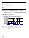
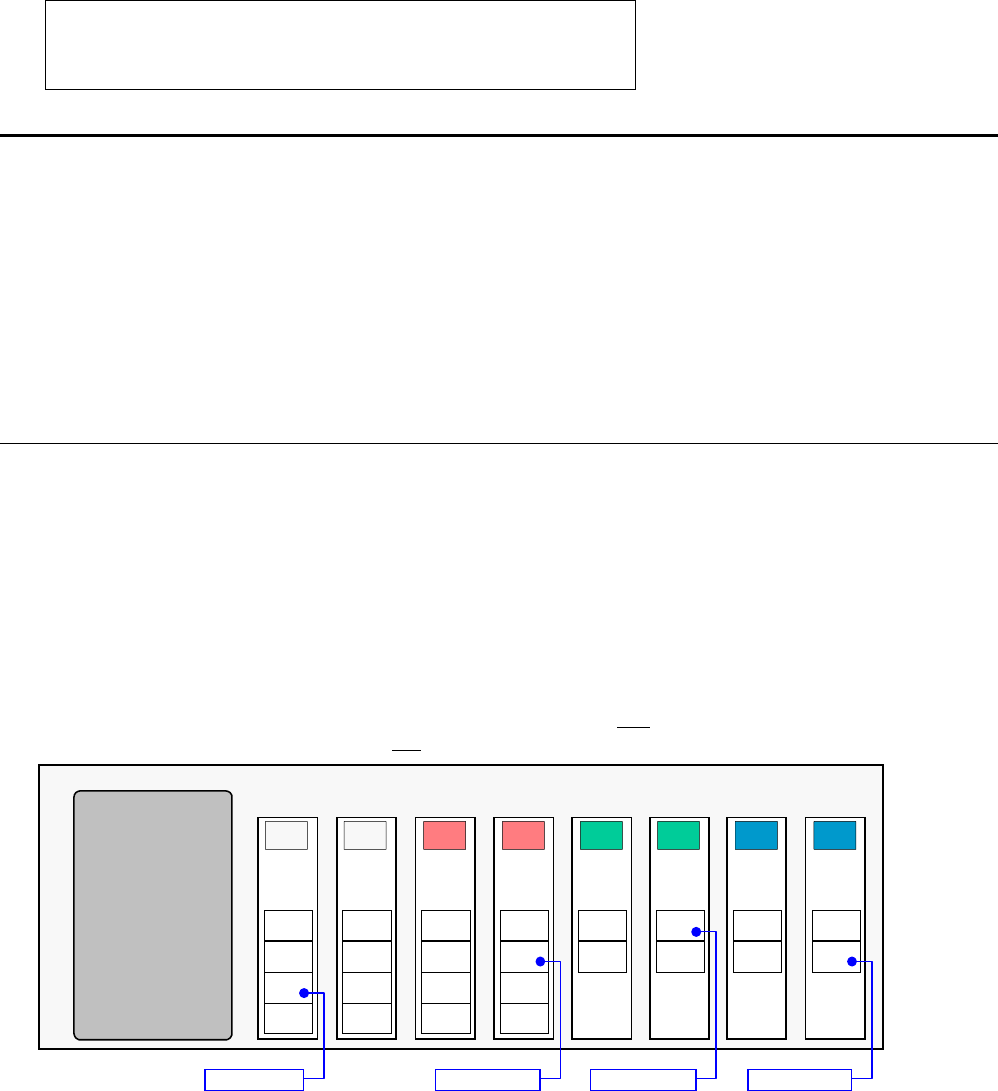
EXAMPLE: OPTO22 is Network Server #2
2\0TIN.3 2\3TOUT.2 2\5TANO.1 2\7TANI.2
page 43