


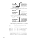

n
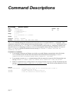
NTMPRI
i,
i,
i,
i
Network Server #
Range: 1-6
# of Allen-Bradley data file
# of first element in AB data file
(beginning of range)
# of elements in range
# of first integer variable (
VARI
) in 6K
(beginning of range, max value is 225)
EXAMPLE:
IF:
•
Allen-Bradley PLC is server #5
•
The PLC’s integer data file 9 has 30
elements. Use data elements 15-29
(15 elements total) for integer data
that is to be shared with the 6K.
•
Use the 6K’s integer variables 35-49
(15 variables total) to store the data
from the PLC.
The required mapping command is:
5NTMPRI9,15,15,35
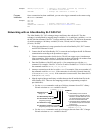
• Use the
NTMPWB
command to write up to 50 binary values from
VARB
variables in
the 6K to binary elements in a PLC’s binary file.
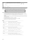
n
NTMPWB
i,
i,
i,
i
Network Server #
Range: 1-6
# of Allen-Bradley data file
# of first element in AB data file
(beginning of range)
# of elements in range
# of first binary variable (
VARB
) in 6K
(beginning of range, max value is 125)
EXAMPLE:
IF:
•
Allen-Bradley PLC is server #5
•
In the PLC’s binary data file 3, use
data elements 0-14 (15 elements
total) for binary data that is to be
transmitted from the 6K.
•
Use the 6K’s binary variables 20-34
(15 variables total) to store the data
to be transmitted to the PLC.
The required mapping command is:
5NTMPWB3,0,15,20
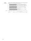
• Use the
NTMPWI
command to write up to 50 integer values from
VARI
variables in
the 6K to a integer elements in a PLC’s integer file.
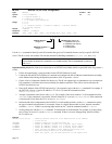
n
NTMPWI
i,
i,
i,
i
Network Server #
Range: 1-6
# of Allen-Bradley data file
# of first element in AB data file
(beginning of range)
# of elements in range
# of first integer variable (
VARI
) in 6K
(beginning of range, max value is 225)
EXAMPLE:
IF:
•
Allen-Bradley PLC is server #5
•
The PLC’s integer data file 9 has 30
elements. Use data elements 0-14
(15 elements total) for integer data
to be transmitted from the 6K.
•
Use the 6K’s integer variables 20-34
(15 variables total) to store the data
to be transmitted to the PLC.
The required mapping command is:
5NTMPWI9,0,15,20
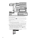
7. Set the polling rate with the
NTPOLL
command. 50 milliseconds is recommended. For
example, to set the polling rate to 50 ms on Server #5, use the
5NTPOLL50
command. If
there is an error during polling, Error Status bit #24 will be set (see
ER
,
TER
or
TERF
).
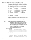
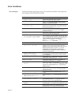
Example
NTADDR172,34,54,123 ; Set the IP address of the 6K
OPTEN0 ; Disable the option card (for Fieldbus units only)
RESET
NTFEN2 ; Enable network function on 6K
RESET
5NTIP1,172,34,54,124 ; Identify network server #5 as an Allen Bradley PLC
; at IP address 172.34.54.124
5NTCONN1 ; Connect to network server #5
5NTMPRB11,7,1,106 ; File 11, element 7 in the AB PLC is mapped to the 6K's
; binary variable VARB106
5NTMPRI20,5,2,128 ; File 20, elements 5-6 in the AB PLC are mapped to
; the 6K's integer variables VARI128-VARI129, respectively
5NTMPWB11,3,4,100 ; File 11, elements 3-6, in the AB PLC are mapped to
; the 6K's binary variables VARB100-VARB103
5NTMPWI20,3,2,120 ; File 20, elements 3-4, in the AB PLC are mapped to
; the 6K's integer variables VARI120-VARB121
5NTPOLL50 ; Start polling network server #5, set interval to 50 ms.
; *********************************************************************
; The 6K's VARB106 will read from the PLC's File 11, element 7.
; The 6K's VARI128-VARI129 will read from the PLC's File 20, elements 5-6.
; The PLC's File 11, elements 3-6 will read from the 6K's VARB100-VARB103.
; The PLC's File 20, elements 3-4 will read from the 6K's VARI120-VARB121.
; *********************************************************************
page 13