


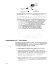

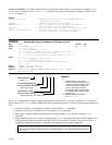
NTIO
Network I/O (OPTO22) Configuration
Type:
Network
Product Rev
Syntax:
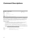
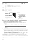
<!><n>\<m>NTIO<i>
Units:
n = network server #
m = OPTO22 I/O module #
i = I/O module type identifier
Range:
n = 1-6
m = 0-7
i = 1 (digital inputs), 2 (digital outputs), 3 (analog inputs),
or 4 (analog outputs)
Default:
0\0NTIO0
Response:
2\3NTIO: *2\3NTIO2
See Also:
\ANI,
[
\ANI
],
\ANO,
[
\ANO
],
\IN,
NTCONN,
NTIP,
\OUT,
[
\OUT
],
\TIO
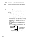
6K 5.3
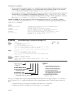
n
\
m
NTIO
<i>
Module # on Server “n”
Range: 0-7
Network Server #
Range: 1-6
Module Type. Options are:
1 = Digital/Discrete Inputs
2 = Digital/Discrete Outputs
3 = Analog Inputs
4 = Analog Outputs
Use the
NTIO
command to identify to the 6K controller the type(s) of I/O modules that are used by a specific OPTO22
server. The 6K, in turn, can use these I/O with the network I/O handling commands (
\IN
,
\OUT
,
\ANI
, and
\ANO
).
Saved in Non-Volatile Memory
This command is saved in the controller’s non-volatile memory, and is remembered on power-up
and RESET.
Implementation process for client/server connection to an OPTO22 unit (further details are provided in the Programmer’s
Guide):
1. Follow the manufacturer’s setup procedure for the OPTO22 Ethernet I/O rack.
2. Connect the 6K and OPTO22 products in a network and configure the 6K for Ethernet communication according
to the Ethernet Networking configuration procedures in the Programmer’s Guide
3. Choose a Server Connection Number for this device. The 6K can support up to 6 simultaneous server connections.
Pick a number (1-6) that has not been used already for another connection. This will be used to reference the
OPTO22 unit from now on.
4. Enter the IP address of the OPTO22 and specify a 2 for connection type with the
NTIP
command. For example, if
the OPTO22 is Server #3 and its IP address is 172.20.34.170, then the command would be
3NTIP2,172,20,34,170
.
5. Attempt a connection to the device with
NTCONN
. For example, if the server number is 3, the command would be
3NTCONN1
. If the connection is successful, Network Status bit #1 is set (see
NTS
,
TNTS
,
TNTSF
). If the connection
is unsuccessful, Error Status bit #23 is set (see
ER
,
TER
,
TERF
).
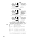
6. Inform the 6K of the configuration of the OPTO22. For each module position, use the
NTIO
command to specify
the type of module in that position. For example, if there is a digital input module in slot 0, then the command
would be
3\0NTIO1
. If there is an Analog Input module in slot 7, then the command would be
3\7NTIO3
.
7. Set the polling rate with the
NTPOLL
command. 50 milliseconds is recommended. For example, to set the polling
rate to 50 ms on server #3, use the
3NTPOLL50
command. If there is an error during polling, then Error Status
bit #24 will be set.
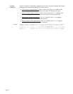
Example:
2NTIP2,172,54,125,34 ; Identify network server #2 as an OPTO22 device at IP address
; 172.54.125.34
2NTCONN1 ; Attempt connection to network server #2
2\0NTIO1 ; Server #2 (OPTO22), module 0 is a digital input module
2\1NTIO2 ; Server #2 (OPTO22), module 1 is a digital output module
2\2NTIO3 ; Server #2 (OPTO22), module 2 is an analog input module
2NTPOLL50 ; Start polling the OPTO22 (start reading and writing I/O),
; set the polling interval to 50 milliseconds.
; After this point, you can read and write to the inputs with
page 19