


16
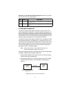
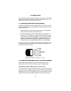
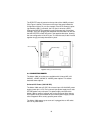
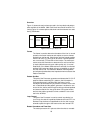
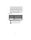
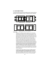
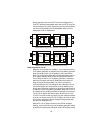
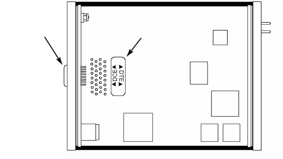
The DCE/DTE strap is located on the top side of the 1088/D pc board
(See Figure 9, below). The arrows on the top of the strap indicate the
configuration of the X.21 port (for example, if the DCE arrows are point-
ing toward the DB-15 connector, the X.21 port is wired as a DCE).
Change the DCE/DTE orientation by pulling the strap out of its socket,
rotating it 180º, then plugging the strap back into the socket. You will see
that the DCE/DTE arrows now point in the opposite directions, showing
the new configuration of the X.21 port. To close the case, fit the 2 halves
together snugly and snap them back in place.
Figure 9.
Setting the DCE/DTE Strap
4.4 CONNECTING POWER
The Model 1088 (all versions) are available with Universal AC (100-
240VAC), 120VAC, 230VAC or -48VDC power options. This section
describes these options.
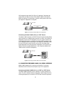
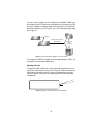
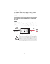
Universal AC Power (100–240 VAC)
The Model 1088 uses a 5 VDC, 2A universal input 100–240 VAC, power
supply (center pin is +5V). The universal input power supply has a male
IEC-320 power entry connector. This power supply connects to the
Model 1088 by means of a barrel jack on the rear panel. Many interna-
tional power cords are available for the universal power supply (Please
refer to Appendix B for country-specific power cords.
The Model 1088 powers up as soon as it is plugged into an AC outlet--
there is no power switch.
DCE/DTE Strap
DB-15 Connector