


8
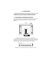
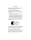
Configuration DIP Switch Set “S2”
Switches S1-1 through S1-8 may be used to configure CO/CP operation,
line framing and coding, CRC-4 operation, and DTE initiated loop diag-
nostics. Default settings of S1 switches are shown in Table 1.
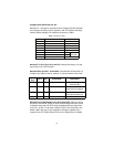
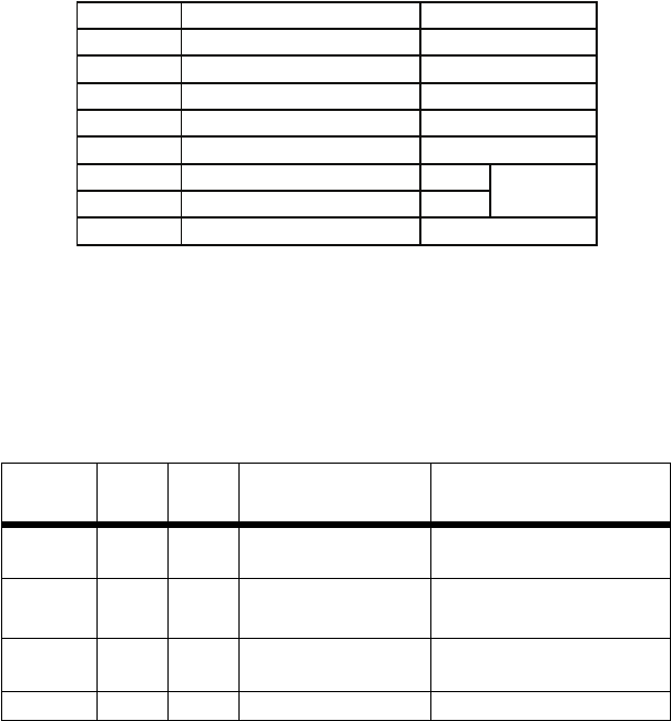
Table 1:
S2 Summary Table
Switch S2-1, S2-2, S2-3, S2-4, and S-5.
Reserved for factory use and
must remain in the OFF Position.
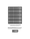
Switches S2-6 and S2-7: Clock Mode.
Use Switches S2-6 and S2-7 to
configure the 1088 for internal, external, or receive recover clock mode.
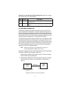
Switch S2-8: Enable/Disable Loop Tests from DTE.
Switch S2-8 may
be used to allow Model 1088/C to enter loopback diagnostic tests (Local
or Remote) when the V.35 DTE raises the appropriate loop request pin
(LLB: Pin L or RDL: Pin N). When Switch S2-8 is in the On position, the
Model 1088/C will enter Local Loopback or Remote Loopback at the
request of the DTE. When Switch S2-8 is in the Off position, the Model
CO/CP
Unit
S2-6 S2-7 Clock Mode Description
CO On On Internal Transmit clock gener-
ated internally
CO Off On External (DTE) Transmit clock derived
from terminal interface
CP On Off Receive Recover Transmit clock derived
from the received line
Off Off Reserved
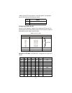
Position Function
S2-1 Reserved
S2-2 Reserved
S2-3 Reserved
S2-4 Reserved
S2-5 Reserved
S2-6 Clock Mode On
S2-7 Clock Mode Off
S2-8 Enable Loop from DTE
Off Disabled
Off
Off
Receive
Recover
Off
Off
Off
Factory Default