


2
CONTENTS
1.0 Warranty Information ................................................................. 4
1.1 Radio and TV Interference............................................................ 4
1.2 CE Notice...................................................................................... 4
1.3 Service.......................................................................................... 5
2.0 General Information.................................................................... 6
2.1 Features........................................................................................ 6
2.2 Description.................................................................................... 6
3.0 Configuration .............................................................................. 7
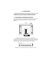
3.1 Configuring the Hardware DIP Switches ...................................... 7
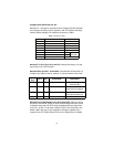
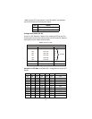
Configuration DIP Switch Set “S2” ............................................... 8
Switch S2-1, S2-2, S2-3, S2-4, and S-5 ................................ 8
Switches S2-6 and S2-7: Clock Mode ................................... 8
Switch S2-8: Enable/Disable Loop Tests from DTE .............. 8
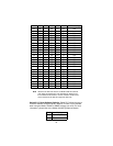
Configuration Switch Set “S3” ...................................................... 9
Switch S3-1: DTE Rate ......................................................... 9
Switch S3-7: Reset Software Defaults ................................ 10
Switch S3-8: Transmit Data (TD) Sampling Point ............... 11
3.2 NetLink Plug-and-Play ................................................................ 11
4.0 Installation................................................................................. 13
4.1 Connecting the Twisted Pair Interface........................................ 13
4.2 Connecting the Model 1088/C (V.35) Serial Interface ................ 13
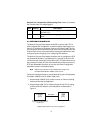
Connecting the Model 1088/C (V.35) to a “DTE” Device............ 13
Connecting the Model 1088/C (V.35) to a “DCE” Device ........... 14
4.3 Connecting the Model 1088/D (X.21) Serial Interface ................ 14
Connecting the Model 1088/D (X.21) to a “DCE” or
“DTE” Device.............................................................................. 14
Opening the Case....................................................................... 15
4.4 Connecting Power ...................................................................... 16
Universal AC Power (100–240 VAC).......................................... 16
120 VAC Power (US).................................................................. 17
230 VAC Power (International)................................................... 17
DC Power ................................................................................... 17
5.0 Operation................................................................................... 18
5.1 Power-Up.................................................................................... 18
5.2 LED Status Monitors................................................................... 18
Model 1088 LED Descriptions Chart .......................................... 19
5.3 Test Modes................................................................................. 19
Overview..................................................................................... 20
5.4 Loops and Patterns..................................................................... 22
Using the V.52 (BER) Test Pattern Generator ........................... 26
A Specifications ........................................................................... 27
A.1 Clocking Modes .......................................................................... 27
A.2 DTE Rate ..................................................................................... 27
A.3 DTE Interface .............................................................................. 27