


26
units enable the 511/511E pattern within 4 seconds of each
other, both units will be transmitting and receiving the 511/511E
pattern. Both framers are now receiving unframed data and will
restart after one minute. The 511/511E pattern generators will
TimeOut after 45 seconds re-enabling the normal data path.
The ER led will begin flashing until the user terminates the test.
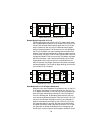
Using the V.52 (BER) Test Pattern Generator
To use the V.52 BER tests in conjunction with the Remote Digital Loop-
back tests (or with Local Line Loopback tests), follow these instructions:
1. Locate the “511/511E” toggle switch on the front panel of the 1088
and move it UP. This activates the V.52 BER test mode and trans-
mits a “511” test pattern into the loop. If any errors are present, the
local modem’s red “ER” LED will blink sporadically.
2. If the above test indicates no errors are present, move the V.52 tog-
gle switch DOWN, activating the “511/E” test with errors present. If
the test is working properly, the local modem's red “ER” LED will
glow. A successful “511/E” test will confirm that the link is in place,
and that the Model 1095’s built-in “511” generator and detector are
working properly.
Note
The above V.52 BER tests can be used independently of the
Remote Digital Loopback tests. This requires two operators: (1)
to initiate and monitor the tests at the local Model 1088, and (2)
to do the same at the remote Model 1088. In this case, the test
pattern sent by each Model 1088 will not be looped back, but will
be transmitted down the line to the other Model 1088. While one
operator initiates test, the other monitors for errors.