19
• Only at power up, blinks once every 200 ms if the DTE Rate is
set to an unsupported settings
TM
Glows yellow to indicate that the Model 1095 has been placed
in Test Mode. The unit can be placed in test mode by the local
user or by the remote user. The TM LED will flash for 400msec
when a valid packet is received from the Model 1001MC.
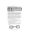
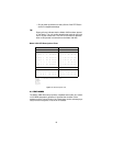
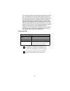
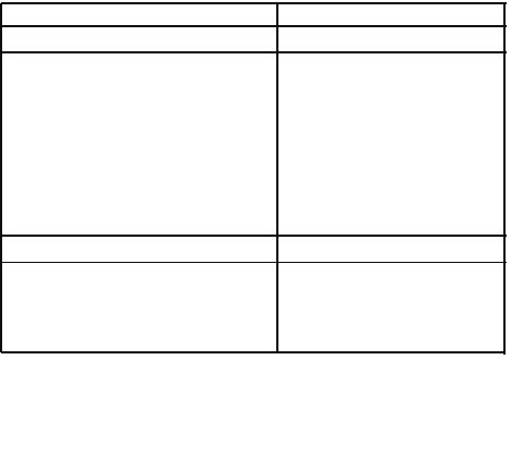
Model 1088 LED Descriptions Chart
Figure 12.
LED descriptions chart
5.3 TEST MODES
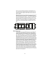
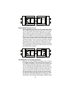
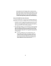
The Model 1088 offers two proprietary loopback test modes, plus a built-
in V.52 BER test pattern generator to evaluate the condition of the
modems and the communication link. These tests can be activated phys-
ically from the front panel or via the DTE interface.
Clock (CO) Internal 768Kb No DTE Clock (CP) R/R No DTE
TD RD DSL NS ER TM TD RD DSL NS ER TM
Power ON G O off ON off off O O off ON off off
DSL Link G O G off off off O G G off off off
Link Brk G O off off off off O O off off off off
Brk+ 10s G G off ON off off O O off ON off off
RDL G G G off off ON O G G off off ON
RDL+511 G G off off off ON O G off off off ON
With DTE Connected With DTE Connected
Mark O O G off off off O O G off off off
Space G G G off off off G G G off off off
Data GO GO G off off off GO GO G off off off
Link Brk = DSL Link Broken
Brk+10s = 10 Seconds following Link Break
G=GREEN
O=ORANGE
ON= ON
off= OFF
Y=yellow


