


Introduction 22
Model 3088 Series User Manual 2 • Configuration
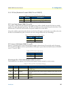
Configuring the DIP switches
The Model 3088 is equipped with two sets of DIP switches, which you can use to configure the RocketLink-G for a
broad range of applications. This section describes switch locations and discusses the configuration options available.
Note
By default, the RocketLink-G’s DIP switches are all set to “ON” so the
NTU can be configured via RocketLink Plug ‘n’ Play from a 3096RC. If
that is how you will be configuring the NTU, skip ahead to section “Con-
sole” on page 32. Otherwise, read the following sections to manually config-
ure the DIP switch settings.
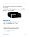
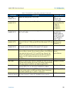
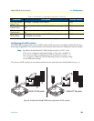
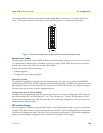
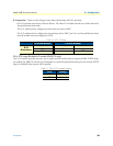
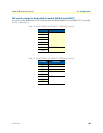
The two sets of DIP switches are externally accessible from the underside of the Model 3088 (see figure 4).
Figure 4. Underside of Model 3088 showing location of DIP switches
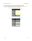
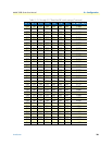
DSL Error Monitor
Interval Time
The length, in seconds, of an interval. 1–255
DSL Error Monitor
Interval Count
The number of errored intervals allowed before restarting the DSL
link.
1–255
DSL Error Monitor
Total Intervals
The number of intervals to inspect before disabling the error mon-
itor.
0–255
DSL Error Monitor
Startup Delay
The length, in seconds, to wait after DSL link comes up before
enabling the error monitor.
0–255
a. For T1 operation, pass framing must be enabled (see Pass Framing parameter for details).
Table 2. RocketLink-G configurable parameters (Continued)
Parameter Description Possible Values
G
.7
0
3
/
G
.
7
0
4
T
e
s
t
M
o
d
e
s
M
o
d
e
l
1
1
9
4
E
S
in
g
le
M
o
d
e
F
i
b
e
r
-
Q
u
a
d
G
.
7
0
3
/
G
.
7
0
4
M
o
d
e
m
12 34567 8
ON
S1
12 34567 8
ON
S2
1 2 3 4 5 6 7 8
ON
1 2 3 4 5 6 7 8
ON
S1
S2
3088 C/D Models
G
.
7
0
3
/
G
.
7
0
4
T
e
s
t
M
o
d
e
s
M
o
d
e
l
1
1
9
4
E
S
in
g
l
e
M
o
d
e
F
i
b
e
r
-
Q
u
a
d
G
.
7
0
3
/
G
.
7
0
4
M
o
d
e
m
12 34567 8
ON
S1
12 34567 8
ON
S2
1 2 3 4 5 6 7 8
ON
1 2 3 4 5 6 7 8
ON
S1
S2
3088 K/T Models
RocketLink-G NTU
RocketLink-G NTU