


Installation 44
Model 3088 Series User Manual 3 • RocketLink-G installation
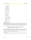
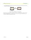
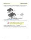
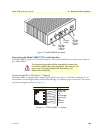
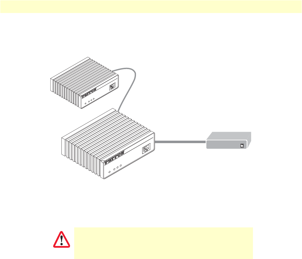
circuit cable. When connecting the V.35 interface of the Model 3088/CA to your DCE device (see figure 9),
use a V.35 tail circuit cable. Some applications may also require the installation of a tail-circuit buffer to
account for small differences in clock frequency between the 3088/CA and the V.35 DCE (multiplexer).
Figure 9. Connecting the Model 3088/CA to V.35 Serial DCE
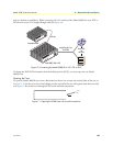
Connecting the Model 3088/D (X.21) serial interface
Model 3088/D supports X.21 serial port connections. This section describes how to connect the serial ports to
your X.21 equipment.
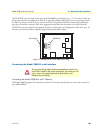
Connecting the Model 3088/D (X.21) to a “DCE” or “DTE” device
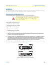
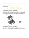
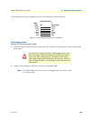
The Model 3088/D provides an X.21 interface on a DB-15 female connector. The X.21 interface default con-
figuration is DCE for connection to DTE (data terminal equipment) such as a router. However, the X.21
interface on the Model 3088/D may be configured as DTE (data terminal equipment) for connection to DCE
The interconnecting cables shall be acceptable for external use
and shall be rated for the proper application with respect to volt-
age, current, anticipated temperature, flammability, and
mechanical serviceability.
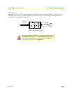
Tail-circuit cable
DSL Span
Model 3088/CA (DCE)
Remote Model 3088
(DCE)
RocketLink™-G NTU
DSL
Terminal
TM/ERR
Power
Console
RocketLink™-G NTU
DSL
Terminal
TM/ERR
Power
Console
G.703 E1 NTU
CAUTION