


Installation 49
Model 3088 Series User Manual 3 • RocketLink-G installation
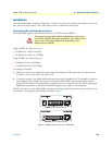
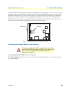
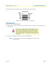
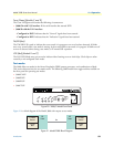
Use the following connection diagram to connect the 120 ohm E1 network channel.
Figure 17. RJ-45 cable diagram for T1 connection
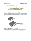
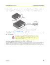
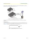
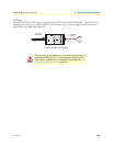
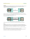
Connecting power
External AC universal power supply
1. Connect the power cord from the AC socket to the IEC-320 power entry connector on the universal input
power supply.
2. Connect the barrel plug to the Power connector on the Model 3088.
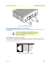
Note
The Model 3088 powers up as soon as it is plugged into an AC outlet—there
is no power switch.
The external AC adaptor shall be a listed limited power source
that incorporates a disconnect device and shall be positioned
within easy reach of the operator. Ensure that the AC power
cable meets all applicable standards for the country in which it is
to be installed, and that it is connected to a wall outlet which has
earth ground.
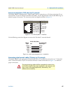
RJ-48C Cable (8-Wire)
T1
Network signal
3088/T
Signal Pin #
RX (Ring)
RX (Tip)
Shield
TX (Ring)
TX (Tip)
Shield
1
2
3
4
5
6
TX (Ring)
TX (Tip)
Shield
RX (Ring)
RX (Tip)
Shield
CAUTION