


Hardware Installation 15
Model 3124 User Manual 2 • Hardware Installation
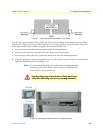
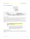
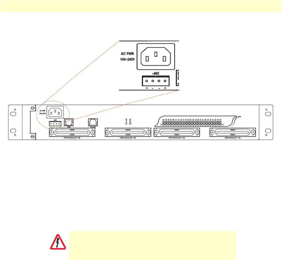
Power and Ground Connections
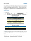
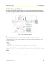
Figure 7. Model 3124 DC and AC Power Connections
DC Power Connection
The DC power interface is a 4-pin terminal block with polarity signs on the front panel of the DSLAM.
The Model 3124 can be powered from two –48V DC power supply. The DC power connector is a 4P termi-
nal block; 2P is for accommodating one DC power input and other 2P is for accommodating another DC
power input. The DC power should be connected to a well-fused power supply.
After completing chassis installation, please apply power to the fused power distribution panel feeding the chas-
sis. When using a DC voltmeter, please check for proper voltage: -72V ~ -36V DC, and make sure that the
polarity is correct.
Note
It is recommended that the -48VDC power be supplied directly and
independently by a power feeding system and also avoid having a par
-
allel or mutual connection with other -48VDC power supplier of
telecom equipment. This is to guarantee our products against inter
-
ferences by other equipment while they are working.
AC Power Connection (Option)
If your Model 3124 uses AC power, connect the AC power cord to the AC supply socket on the front panel of
the DSLAM (refer to
Figure 7), and plug the cord into the external power source. The voltage must be 100 to
240 VAC.
Ensure that all power sources to the chassis (power distribution panel) are
turned off during the connection.
WARNING