


Hardware Installation 16
Model 3124 User Manual 2 • Hardware Installation
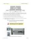
Ground Connection
This section provides the grounding rule for the Model 3124. All remote system sites must be properly
grounded for optimum system performance.
In Central Office. There should be a CO GND that is adequately grounded. If the measured resistance from
the grounding screw (on the rear panel of the DSLAM, refer to Figure 1-4) to CO GND is less than 5 Ohm,
then it can be assumed that the system is well grounded. If the measured resistance is larger than 5 Ohm, it is
recommended to connect the grounding screw to CO GND using #14 or #12 AWG wire gauge conductor.
In Remote Cabinet. The Model 3124 should be grounded by connecting a #14 or #12 AWG conductor
between the grounding screw (on the rear panel of the DSLAM, refer to Figure 1-4) and the earth ground or
main grounding bar. The resistance between the chassis and the grounding bar should be less than 25 Ohm.
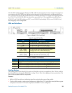
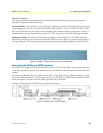
Figure 8. Model 3124 grounding screw on the rear panel
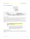
Connecting the ADSLx and POTS interfaces
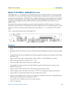
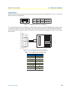
The Model 3124 supports 24/48 ADSLx subscribers per box. There are four RJ-21 50-pin female connectors
on the front panel of the system. Two connectors are for the ADSL line and two connectors are for the POTS
interface.
To connect the subscriber lines, use cables with the RJ-21 50-pin male connector. When installing, just plug
the end of a cable with the RJ-21 50-pin male connector into the POTS or LINE interface female connector
on the front panel. The other side of the cable is generally tied to the MDF.
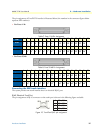
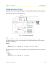
The figure below shows the Line/POTS port position of the system:
Figure 9. Model 3124 Line/POTS ports