


Hardware Installation 18
Model 3124 User Manual 2 • Hardware Installation
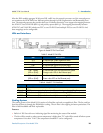
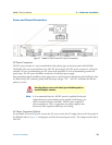
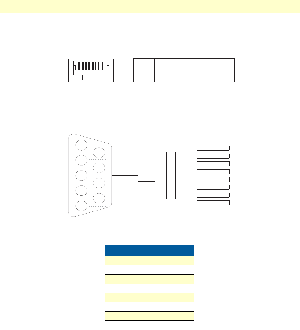
Console Port
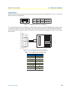
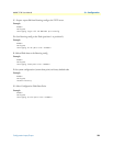
The Console interface on the front panel is the main control interface of the Model 3124. Figure 11 shows the
RJ45 connector pin assignment:
Figure 11. Console Port RJ-45 pin assignment
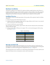
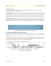
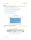
To connect the host PC to the console port, a RJ45 (male) connector-to-RS232 DB9 (female) connector cable
is required. The RJ45 connector of the cable is connected to the Console port of the DSLAM; the DB9 con
-
nector of the cable is connected to the PC COM port. The DTE relative pin assignment of the console cable is
shown below:
Figure 12. Pin assignment of Console Interface
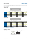
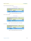
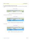
Table 9. Pin Assignment of Console Cable
DB-9F RJ-45M Pin
-- 1
- 2
Pin 2 RD 3
Pin 3 TD 4
- 5
Pin 5 DGND 6
- 7
- 8
3 4 6 Other pins
TX RX GND Not used
1 2 3 4 5 6 7 8
12345678
1
2
RD
3
TD
4
5
DGND
6
7
8
9
1
8
7
6 (DGND)
5
4 (TD)
2
3 (RD)