Pelco Manual C1921M-G (1/04) 7
UNUSED
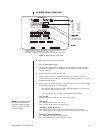
Leave switch 5 OFF. It is not used.
TURBO MODE
Set switch 6 ON to enable the turbo (extra fast) pan feature or OFF to disable.
CAMERA ADDRESS MODE
There are two modes for addressing cameras:
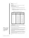
• Set switch 7 ON if you want to address all cameras consecutively from 1-256
(refer to Table A).
• Set switch 7 OFF if you want to address cameras in groups of 16 according to
the multiplexer to which they are connected. For example, multiplexer 1, cameras
1-16; multiplexer 2, cameras 1-16, etc.
PROGRAMMING MODE
Set switch 8 ON to program the multiplexer and camera presets and patterns from the
keyboard. Set to OFF to disable programming.
3. Replace the cover on the back of the keyboard.
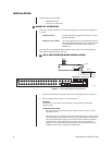
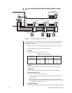
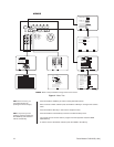
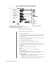
4. The keyboard comes with a 25-foot (7.6 m) data cable with RJ-45 connectors. Plug
one end into the back of the keyboard and the other end into the COM IN connector
on the back of the multiplexer. Refer to Figure 1.
The keyboard receives power from the multiplexer. The LED display lights momen-
tarily when the keyboard receives power and stays on when you enter a
multiplexer address.
The KBD4000 has calibrating software for automatically centering the joystick. Be
certain the joystick remains in the neutral (vertical) position as power is applied to the
keyboard. Do not move or hold down the joystick until after the red digit LEDs have
finished flashing the firmware revision.
5. Peel off the protective covering over the LED display in the keyboard’s upper left
corner.
NOTE:
For distances over
25 feet (7.6 m), you
must
order the KBDKIT(-X) Re-
mote Keyboard Wiring Kit.
Refer to the KBDKIT(-X)
manual for installation
procedures.
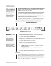
Table A. Camera Numbers with Switch 7 ON
Multiplexer Cameras
9-channel 16-channel
1 1-9 1-16
2 17-25 17-32
3 33-41 33-48
4 49-57 49-64
5 65-73 65-80
6 81-89 81-96
7 97-105 97-112
8113-121 113-128
9 129-137 129-144
10 145-153 145-160
11 161-169 161-176
12 177-185 177-192
13 193-201 193-208
14 209-217 209-224
15 225-233 225-240
16 241-249 241-256


