8 Pelco Manual C1921M-G (1/04)
1B
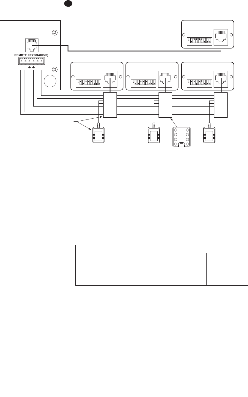
DO A MULTIPLEXER SERVER MODE INSTALLATION
R+R-TT+
LOCAL
KEYBOARD
ON
1234567
ON
1234567
ON
1234567
ON
1234567
1 TX+
2 TX-
3 12VAC
4 12VAC
5 GND
6NC
7 RX-
1 TX+
2 TX-
3 12VAC
4 12VAC
5 GND
6NC
7 RX-
1 TX+
2 TX-
3 12VAC
4 12VAC
5 GND
6NC
7 RX-
ADDRESS #2 (REMOTE)
CONTROLS MONITOR 2
ADDRESS #3 (REMOTE)
CONTROLS MONITOR 3
ADDRESS #4 (REMOTE)
CONTROLS MONITOR 4
ADDRESS #1 (LOCAL)
CONTROLS MONITOR 1
KBDKIT
MULTIPLEXER
WALL BLOCK
1
2
3
45
6
7
8
00017
If the keyboard will be connected to a server that will operate in paired mode configuration,
only addresses 1 and 3 can be used. Refer to the server manual for information about
paired mode configuration.
1. Remove the DIP switch cover plate from the rear of the keyboard (refer to Figure 1).
2. Set the switches (refer to Figure 1 for switch locations).
ADDRESS
Set the keyboard address according to Table B.
Figure 2. Connecting Keyboards to the Server
Table B. Keyboard Addresses
Keyboard Switch Settings
Address 1 2 3
1ONOFF OFF
2 OFF ON OFF
3ONONOFF
4 OFF OFF ON
UNUSED
Switches 4 and 5 must be set OFF. They are not used in multiplexer server mode.
TURBO MODE
Set switch 6 ON to enable the turbo (extra fast) pan feature or OFF to disable.
CAMERA ADDRESS MODE
There are two modes for addressing cameras:
• Set switch 7 ON if you want to address all cameras consecutively from 1-256
(refer to Table A).
• Set switch 7 OFF if you want to address cameras in groups of 16 according to
the multiplexer to which they are connected. For example, multiplexer 1, cameras
1-16; multiplexer 2, cameras 1-16, etc.
PROGRAMMING MODE
Set switch 8 ON to program the multiplexer and server and OFF to disable programming.


