Philips Semiconductors ISP1301 USB OTG Transceiver Eval Kit User’s Guide
UM10028_1 © Koninklijke Philips Electronics N.V. 2003. All rights reserved.
User’s Guide Rev. 1.0—February 2003 13 of 18
6.2.4. Power manager
This block includes the 5.0 V-to-3.3 V regulator and power source selection.
6.2.5. Audio interface
This block provides stereo audio line IN interface and microphone (with pre-amp) OUT interface. Its main
purpose is to demonstrate the carkit application (play audio or voice with carkit).
7. Connector pin information
7.1. DB-25 PC parallel port connector (J10) pin assignment
J10 is used to connect to the PC parallel port through the DB-25 printer cable. Table 7-1 shows its pin assignment.
Table 7-1: DB-25 PC parallel port connector (J10) pin assignment
Pin no Printer port signal ISP1301 evaluation board signal
9 D7 SDAOUT#
11 S7# SDAIN#
15 S3 SCLIN
17 C3# SCLOUT#
10,13,18–25 — GND
1–8,12,14,16, — No connection
7.2. 8-bit microprocessor interface 20 x 2 header (J13) pin assignment
J13 is used to connect to a generic 8-bit parallel bus microprocessor controller. The bus uses the Intel
®
mode.
Required signals include D0–D7, A0, WR_N, RD_N, CS_N, INT1 and INT2. Table 7-2 shows the pin assignment
for J13.
Note: We use a 20 x 2 header to make it compatible with the Philips ISP1362 and ISP1161x ISA interface boards.
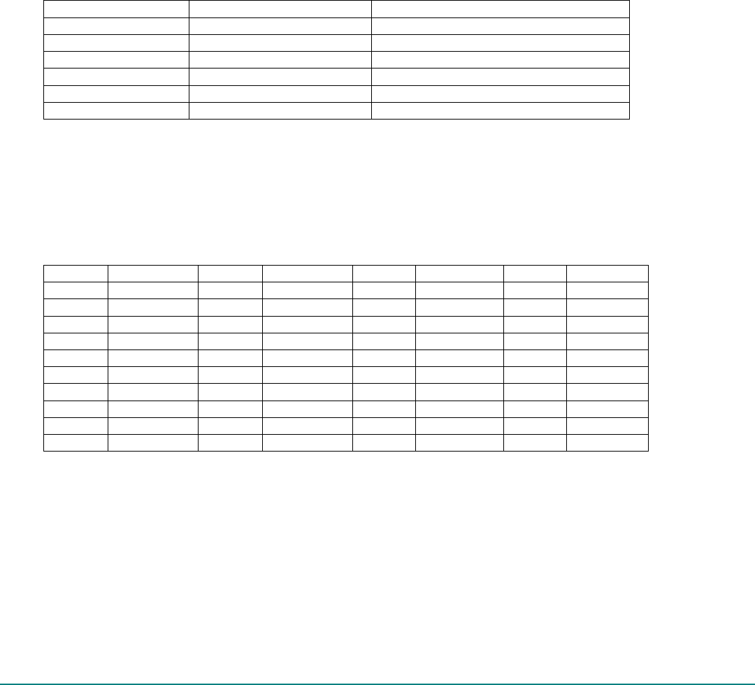
Table 7-2: 8-bit microprocessor-interface 20 x 2 header (J13) pin assignment
[1]
Pin no Pin name Pin no Pin name Pin no Pin name Pin no Pin name
1 GND 11 n. c. 21 D7 31 D2
2 n. c. 12 +3.3 V 22 INT2 32 n. c.
3 n. c. 13 n. c. 23 D6 33 D1
4 CHRG_EN 14 n. c. 24 INT1 34 WR_N
5 n. c. 15 n. c. 25 D5 35 D0
6 n. c. 16 +5.0 V 26 n. c. 36 RD_N
7 n. c. 17 n. c. 27 D4 37 n. c.
8 n. c. 18 +5.0 V 28 n. c. 38 CS_N
9 n. c. 19 GND 29 D3 39 A0
10 +3.3 V 20 n. c. 30 n. c. 40 n. c.
[1] n. c.—Denotes no connection.
Note: An external OTG Controller system can use the CHRG_EN signal to enable or disable +5.0 V from the
V
BUS
line of the mini-AB connector to pin 2 of J2. This is useful when an analog audio carkit is attached and the
carkit can charge the external battery.
7.3. USB OTG Controller interface 8 x 2 header (J8 and J3) pin assignment
Header connectors J8 and J3 are used to connect the ISP1301 to the OTG Controller core. J8 includes the USB
Serial Interface Engine (SIE) signals—DAT_VP, SE0_VM, RCV and OE_TP_INT_N—and I
2
C signals—SDA, SCL and
INT_N. J3 also includes other signals that may be used by selected OTG Controller.


