


Philips Semiconductors ISP1301 USB OTG Transceiver Eval Kit User’s Guide
UM10028_1 © Koninklijke Philips Electronics N.V. 2003. All rights reserved.
User’s Guide Rev. 1.0—February 2003 7 of 18
3.3. USB interface
There are three USB connectors on the ISP1301 evaluation board.
• If an OTG Controller is connected to the ISP1301, the USB port functions as an OTG dual-role device
and only the mini-AB connector (J5) will be used.
• If a Host Controller is connected to the ISP1301, the USB port functions as a host and only the Type-A
connector (J1) will be used.
• If a Device Controller is connected to the ISP1301, the USB port functions as a device and only the Type-
B connector (J4) will be used.
You can use all the three ports at the same time. If you have a system that consists of a USB host port and a
separate device port, then the host port can be connected to J4 and the device port can be connected to J1 using
the standard USB cable. In such a case, the ISP1301 provides only OTG functions to the system; the transceiver
function of the ISP1301 is not used.
3.4. Audio interface
The ISP1301 evaluation board has an interface to support an analog audio carkit application. Connect:
• The audio carkit to the mini-AB connector (J9) on the board;
• The audio input line signal to the SPK LINE IN socket (J6) on the board;
• The audio output line signalto the MIC LINE OUT socket (J7) on the board.
3.5. Reset
For a hardware reset to the ISP1301, press the manual reset switch (SW1). The reset pulse (active LOW) can also
come from the OTG Controller interface (pin 8 of J3).
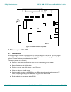
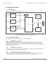
4. Location of major components
Figure 4-1 shows the location of major components on the evaluation board.